


PICAXE 08M control of audio/video cabinet cooling
#PICAXE 08M
#DS18B20
#temperature sensor
#fan controller
#cooling system
#audio/video cabinet
#screw terminals
#LED indicator
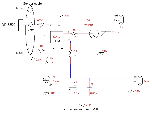
Description: This is a fan controller designed for an audio/video cabinet. It utilizes a PICAXE 08M microcontroller and a DS18B20 temperature sensor. The fan activates at 30 degrees Celsius (approximately 86 degrees Fahrenheit) and deactivates at 28 degrees Celsius (around 82 degrees Fahrenheit). A green LED serves as both an activity indicator and a general temperature indicator. All external connections are facilitated through screw terminals: the left terminal block is designated for the fan, the bottom block for power, and the right terminal block for the DS18B20 sensor. This project was initiated following the replacement of a 12-year-old television with a new 26-inch HD-capable LCD TV, which fits within the existing corner cabinet, the largest that can be accommodated between a brick fireplace and a side wall window. After adjusting the DVD player shelf upward, there remained less than 2 inches (50 mm) of clearance above the new television. Initial testing indicated insufficient ventilation, with a thermometer reading just over 114 degrees Fahrenheit (approximately 46 degrees Celsius)—a rise of 26 degrees Fahrenheit above room temperature. The fan operates at 12 volts and 11 CFM, powered by a regulated 5.2-volt, 1.2-amp supply that also energizes the PICAXE board. The lower voltage reduces fan speed and noise while still providing adequate airflow to limit the temperature rise above the television to 12 or 14 degrees Fahrenheit. A maximum cabinet temperature of 92 degrees Fahrenheit (33 degrees Celsius) in a room maintained at 78 degrees Fahrenheit (approximately 25 degrees Celsius) is deemed acceptable. Installation occurred on September 24, 2006. Following a week of testing, the circuit board will be enclosed in a case with a transparent or translucent cover to maintain visibility of the LED. Note that US/metric conversions are approximate and are intended for thermal management rather than precision applications.
The fan controller circuit operates on a microcontroller-based system designed to monitor and regulate temperature within an enclosed audio/video cabinet. The PICAXE 08M serves as the central processing unit, executing the control logic based on inputs from the DS18B20 temperature sensor. This sensor provides accurate temperature readings, allowing the microcontroller to determine when to activate or deactivate the fan based on predefined temperature thresholds.
The fan is connected to the left terminal block, receiving power from the regulated supply, which also powers the microcontroller. The choice of a 12-volt fan running at a reduced voltage of 5.2 volts ensures a quieter operation while still maintaining sufficient airflow to manage heat dissipation effectively. The fan's airflow rate of 11 CFM is adequate for the cabinet's size, preventing excessive heat buildup above the television.
The green LED indicator provides visual feedback about the system's operational status and serves as an approximate temperature gauge, allowing users to monitor the system's performance at a glance. The inclusion of screw terminals for connections enhances the reliability and ease of installation, facilitating straightforward wiring for the fan, power supply, and temperature sensor.
Overall, this fan controller design exemplifies a practical solution for thermal management in compact electronic enclosures, ensuring the longevity and performance of audio/video equipment while maintaining user-friendly features and efficient operation.This is a fan controller for an audio/video cabinet. It uses a PICAXE 08M and a DS18B20 temperature sensor. The fan is turned on at 30 degrees C (~86 F) and off at 28 degrees C (~82 F). The green LED is the activity indicator and also serves as a "ballpark" temperature indicator. All off-board connections are made via screw terminals. The lef t terminal block for the fan, the bottom block for power, the right terminal block for the DS18B20. This project was initiated when we replaced a 12-year-old TV with a new 26" HD-capable LCD TV (happy 41st anniversary to us ;-) This TV was the largest that would fit in the existing corner cabinet (which is the largest cabinet that will fit between the brick fireplace and the window on the side wall). After moving the DVD player shelf up, there was still less than 2" (50mm) clearance above the new TV.
Initial testing (hand on the upper shelf) indicated this was not enough for adequate ventilation. A thermometer verified this with a reading of just over 114 degrees F (~46 C) - a rise of 26 degrees F above room temperature. The fan is a 12 volt, 11CFM unit running off the regulated 5. 2 volt, 1. 2 amp supply that also powers the PICAXE board. The lower voltage reduces the fan speed (and noise) but the fan still delivers enough air flow to limit the temperature rise at the hottest point (directly above the TV) to 12 or 14 degrees F.
A maximum cabinet temperature of 92 degrees F (33 C) in a room that`s at 78 degrees F (~25 C) is certainly acceptable. This was installed on 24 September 2006. After a week or so of testing, the circuit board will be placed in a case with a transparent or translucent cover (so the LED will remain visible).
Note that US/metric conversions are approximate - I`m not processing silicon wafers, just preventing overheating ;-)
The fan controller circuit operates on a microcontroller-based system designed to monitor and regulate temperature within an enclosed audio/video cabinet. The PICAXE 08M serves as the central processing unit, executing the control logic based on inputs from the DS18B20 temperature sensor. This sensor provides accurate temperature readings, allowing the microcontroller to determine when to activate or deactivate the fan based on predefined temperature thresholds.
The fan is connected to the left terminal block, receiving power from the regulated supply, which also powers the microcontroller. The choice of a 12-volt fan running at a reduced voltage of 5.2 volts ensures a quieter operation while still maintaining sufficient airflow to manage heat dissipation effectively. The fan's airflow rate of 11 CFM is adequate for the cabinet's size, preventing excessive heat buildup above the television.
The green LED indicator provides visual feedback about the system's operational status and serves as an approximate temperature gauge, allowing users to monitor the system's performance at a glance. The inclusion of screw terminals for connections enhances the reliability and ease of installation, facilitating straightforward wiring for the fan, power supply, and temperature sensor.
Overall, this fan controller design exemplifies a practical solution for thermal management in compact electronic enclosures, ensuring the longevity and performance of audio/video equipment while maintaining user-friendly features and efficient operation.This is a fan controller for an audio/video cabinet. It uses a PICAXE 08M and a DS18B20 temperature sensor. The fan is turned on at 30 degrees C (~86 F) and off at 28 degrees C (~82 F). The green LED is the activity indicator and also serves as a "ballpark" temperature indicator. All off-board connections are made via screw terminals. The lef t terminal block for the fan, the bottom block for power, the right terminal block for the DS18B20. This project was initiated when we replaced a 12-year-old TV with a new 26" HD-capable LCD TV (happy 41st anniversary to us ;-) This TV was the largest that would fit in the existing corner cabinet (which is the largest cabinet that will fit between the brick fireplace and the window on the side wall). After moving the DVD player shelf up, there was still less than 2" (50mm) clearance above the new TV.
Initial testing (hand on the upper shelf) indicated this was not enough for adequate ventilation. A thermometer verified this with a reading of just over 114 degrees F (~46 C) - a rise of 26 degrees F above room temperature. The fan is a 12 volt, 11CFM unit running off the regulated 5. 2 volt, 1. 2 amp supply that also powers the PICAXE board. The lower voltage reduces the fan speed (and noise) but the fan still delivers enough air flow to limit the temperature rise at the hottest point (directly above the TV) to 12 or 14 degrees F.
A maximum cabinet temperature of 92 degrees F (33 C) in a room that`s at 78 degrees F (~25 C) is certainly acceptable. This was installed on 24 September 2006. After a week or so of testing, the circuit board will be placed in a case with a transparent or translucent cover (so the LED will remain visible).
Note that US/metric conversions are approximate - I`m not processing silicon wafers, just preventing overheating ;-)
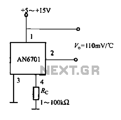
AN6071 application circuit a
The AN6071 application circuit is illustrated. The relationship between the output voltage and temperature is 110 mV/°C.
The AN6071 is a precision temperature sensor designed for applications requiring accurate temperature measurement and monitoring. The output voltage of the AN6071 varies linearly...
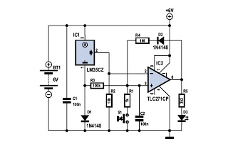
Frost Detector Temperature Sensor Circuit
To determine whether it is freezing, it is necessary to measure the temperature accurately using a reliable temperature sensor. The LM35CZ, which operates between -40 to 110 °C, has been chosen for this purpose. This sensor generates an output voltage...
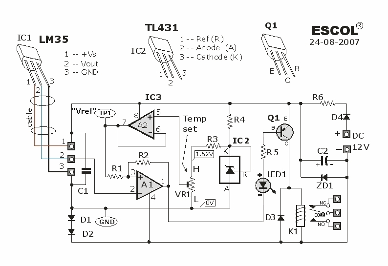
Temperature Controlled Relay Circuit
This temperature-controlled relay circuit is a simple yet highly accurate thermal control circuit that can be used in applications where automatic temperature regulation is required.
The temperature-controlled relay circuit operates by monitoring the ambient temperature using a temperature sensor, such as...
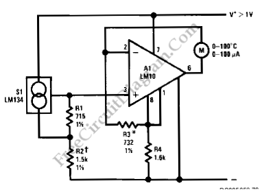
LM134-LM10 Thermometer/Temperature Sensor
Using LM134 and LM10 integrated circuits, a thermometer can be constructed with a sensing range of -55 to 150 °C. The ideal meter for this circuit is a 0-200 µA.
The proposed thermometer circuit utilizes the LM134, a current source IC,...
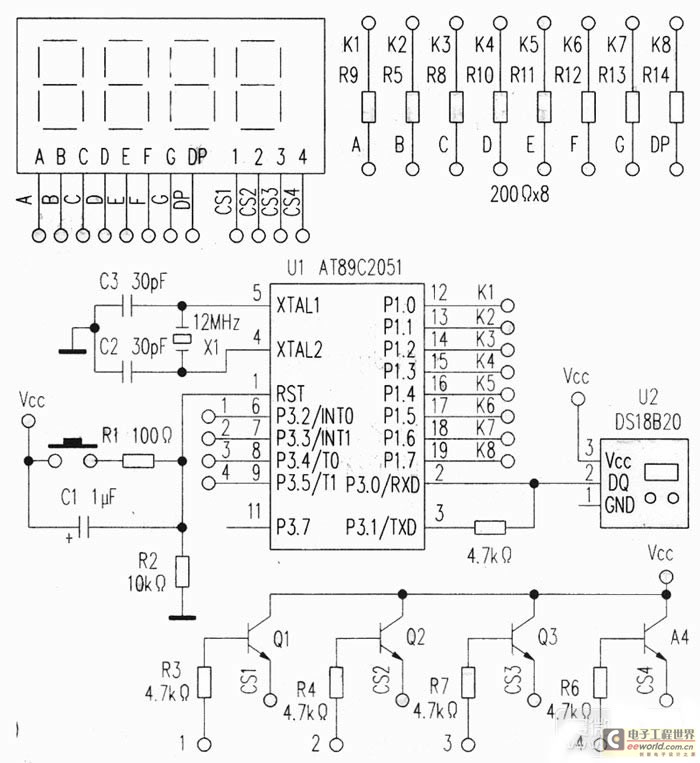
Simply analyse the temperature measurer cipher scheme based on DS18B20 and AT89C2051
This project utilizes a USB port for power supply, employs a DS18B20 temperature sensor for data acquisition, and is controlled by an AT89C2051 microcontroller. A common anode quad-digit seven-segment display is used for output, allowing for temperature measurement visualization. The...
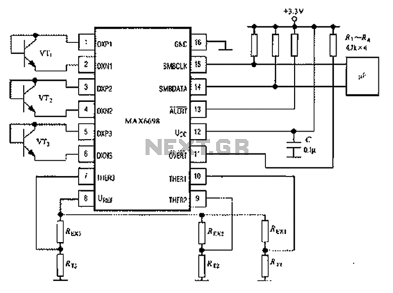
Temperature Sensor MAX6698 7-Channel Smart consisting of circuit diagram
The circuit illustrated in the figure involves the MAX6698 maximum temperature sensor, which utilizes three transistors (VT1 to VT3) and three thermistors (RT1 to RT3). An internal reference voltage source is connected through resistors UREF REX1 to REX3, providing power...

DS1621 PC Thermometer Circuit
The following circuit is a PC thermometer utilizing the DS1621. Features include the ability to plug into any available PC COM port, a temperature range of -20 to 125°C, and the capability to display temperatures in both Celsius (°C) and...
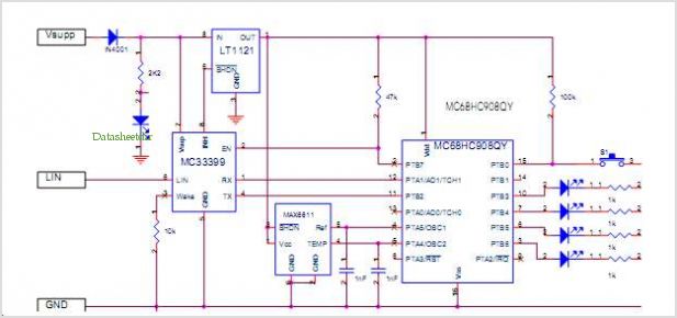
Lin Temperature Sensor Using The Mc68hc908qt/qy Mcu
The LinkSwitch-LP family is designed to replace inefficient line frequency linear transformer-based power supplies with output powers less than 2.5 W in applications such as cell/cordless phones, PDAs, digital cameras, and portable audio players. LinkSwitch-LP may also be used as...
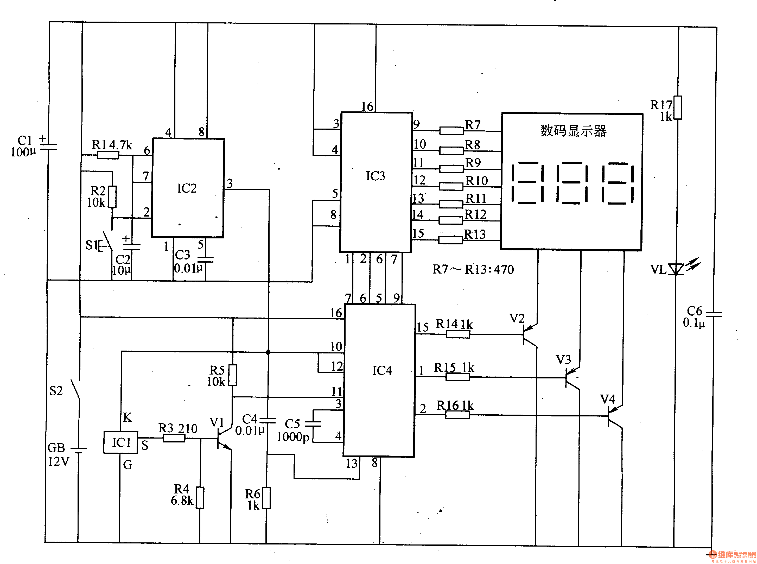
Electronic thermometer(2)
The temperature measuring range of this electronic thermometer is 0-50 degrees Celsius, with a precision of 0.1 degrees Celsius. The measurement results are intuitively displayed on a digital screen. This electronic thermometer circuit consists of a temperature detection circuit, a...