


Space heater controlled by digital thermostat Schematic
#thermostat
#temperature control
#heater
#Eagle
#schematic
#W1 output
#home appliance
#digital control
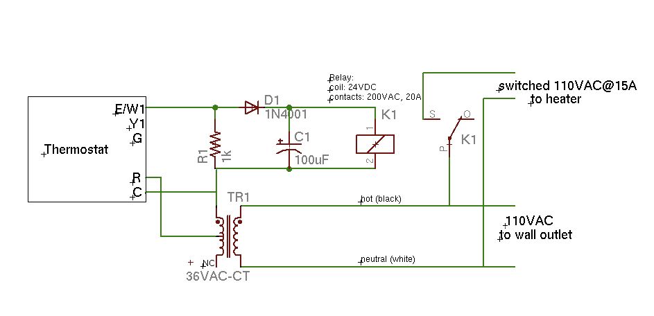
Description: A basic schematic of the circuit is presented, marking the initial experience with Eagle software. It is important to note that only the W1 output of the thermostat is utilized, while C serves as the common connection.
The schematic outlines a simple circuit design where the thermostat's W1 output is connected to a load, such as a heating element or fan, facilitating temperature control in a system. The common terminal, labeled as C, provides a reference point for the circuit, ensuring proper operation of the thermostat.
In a typical configuration, the W1 output activates when the temperature falls below a predetermined threshold, allowing current to flow to the connected load. This action is essential for maintaining the desired environmental conditions. The common terminal (C) is typically connected to the power supply's negative or ground, establishing a complete circuit for the thermostat to function effectively.
For enhanced reliability, it is advisable to include protective components such as a fuse or circuit breaker in the design to prevent overcurrent situations that could potentially damage the thermostat or the load. Additionally, utilizing a relay can provide isolation between the thermostat and the load, allowing the circuit to handle higher power levels while ensuring the thermostat operates within its rated specifications.
Overall, this schematic serves as a foundational representation for a temperature control system, illustrating the essential components and their interconnections. Further refinements may include incorporating additional features such as indicators or more complex control logic, depending on the specific application requirements.Here is a rough schematic of the circuit (also my first experience with Eagle!). Notes: Only the W1 output of the thermostat is used. C is the common..
The schematic outlines a simple circuit design where the thermostat's W1 output is connected to a load, such as a heating element or fan, facilitating temperature control in a system. The common terminal, labeled as C, provides a reference point for the circuit, ensuring proper operation of the thermostat.
In a typical configuration, the W1 output activates when the temperature falls below a predetermined threshold, allowing current to flow to the connected load. This action is essential for maintaining the desired environmental conditions. The common terminal (C) is typically connected to the power supply's negative or ground, establishing a complete circuit for the thermostat to function effectively.
For enhanced reliability, it is advisable to include protective components such as a fuse or circuit breaker in the design to prevent overcurrent situations that could potentially damage the thermostat or the load. Additionally, utilizing a relay can provide isolation between the thermostat and the load, allowing the circuit to handle higher power levels while ensuring the thermostat operates within its rated specifications.
Overall, this schematic serves as a foundational representation for a temperature control system, illustrating the essential components and their interconnections. Further refinements may include incorporating additional features such as indicators or more complex control logic, depending on the specific application requirements.Here is a rough schematic of the circuit (also my first experience with Eagle!). Notes: Only the W1 output of the thermostat is used. C is the common..
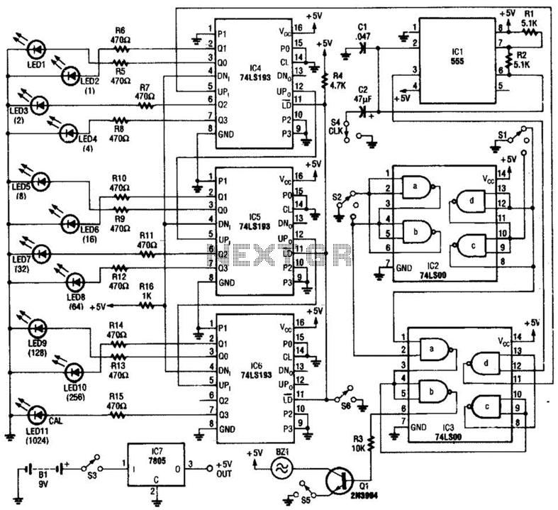
Electronic Thermostat Circuit
A diode, such as the IN4148, has a typical temperature coefficient of -2 mV/°C at a 1 mA diode current. Transistors Q1 and Q2 form a constant current source. Diode D1 serves as the temperature sensor. Integrated circuits ICl-a and...
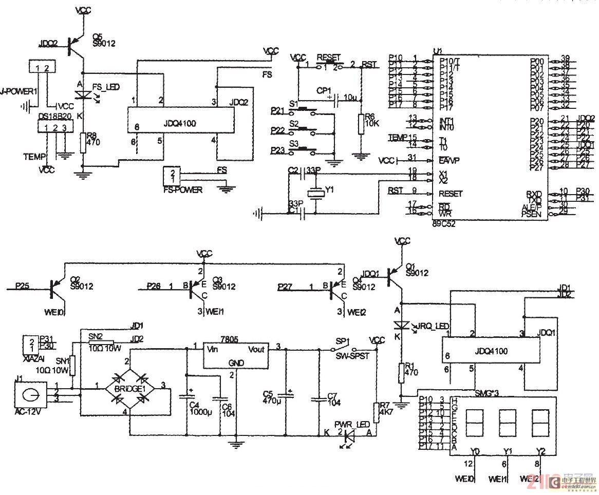
The method of temperature controlling system of producing one-chip computer calorstat is analyzed
The primary principle of the system is to gather real-time temperature data from a temperature sensor using a microcontroller, which then compares this data with pre-defined thermostat values to maintain the desired temperature within a sample container. This text covers...
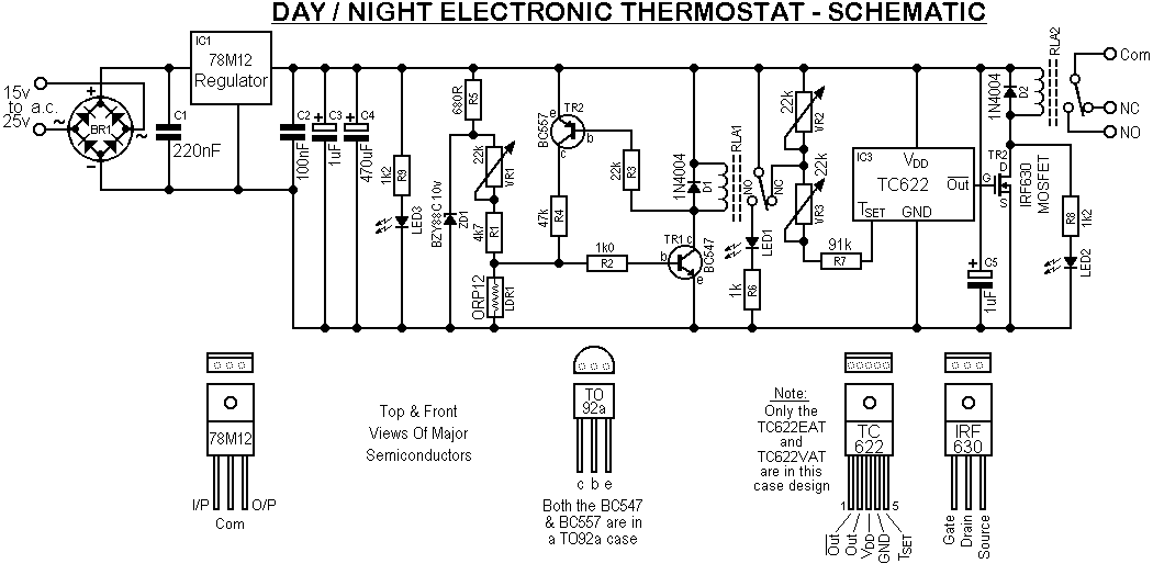
Day / Night Electronic Thermostat
This design was created at the request of an individual to operate a 240V AC heater in an orchid box, maintaining a higher temperature during daylight hours than at night. A simple regulator is employed to achieve a stabilized 12V...
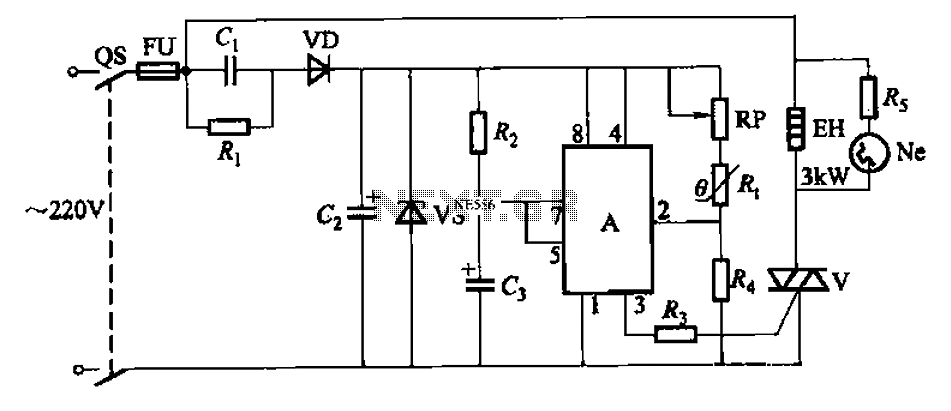
Automatic temperature control circuit
An automatic temperature control circuit is designed for climate control thermostats. Its primary function is to maintain a constant internal temperature using an electric heater (EH). The control mechanism utilizes a negative temperature coefficient thermistor as the temperature sensing element,...
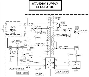
Need to have the circuit schematic for LG 29SA1RL model
The schematic is in PDF format and cannot be sent through this site. It is recommended to check a specific website that contains various schematics, including older posts that might have the schematic needed. A WS-55807 model is experiencing issues...
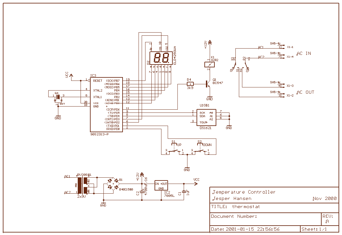
Temperature Controller
Wine doesn't like subzero temperatures, and during wintertime, my wine cellar got pretty cold. There was an electric heating element, but the thermostat was broken, so it was either full burn or nothing. That's how the temperature monitor/controller came to...
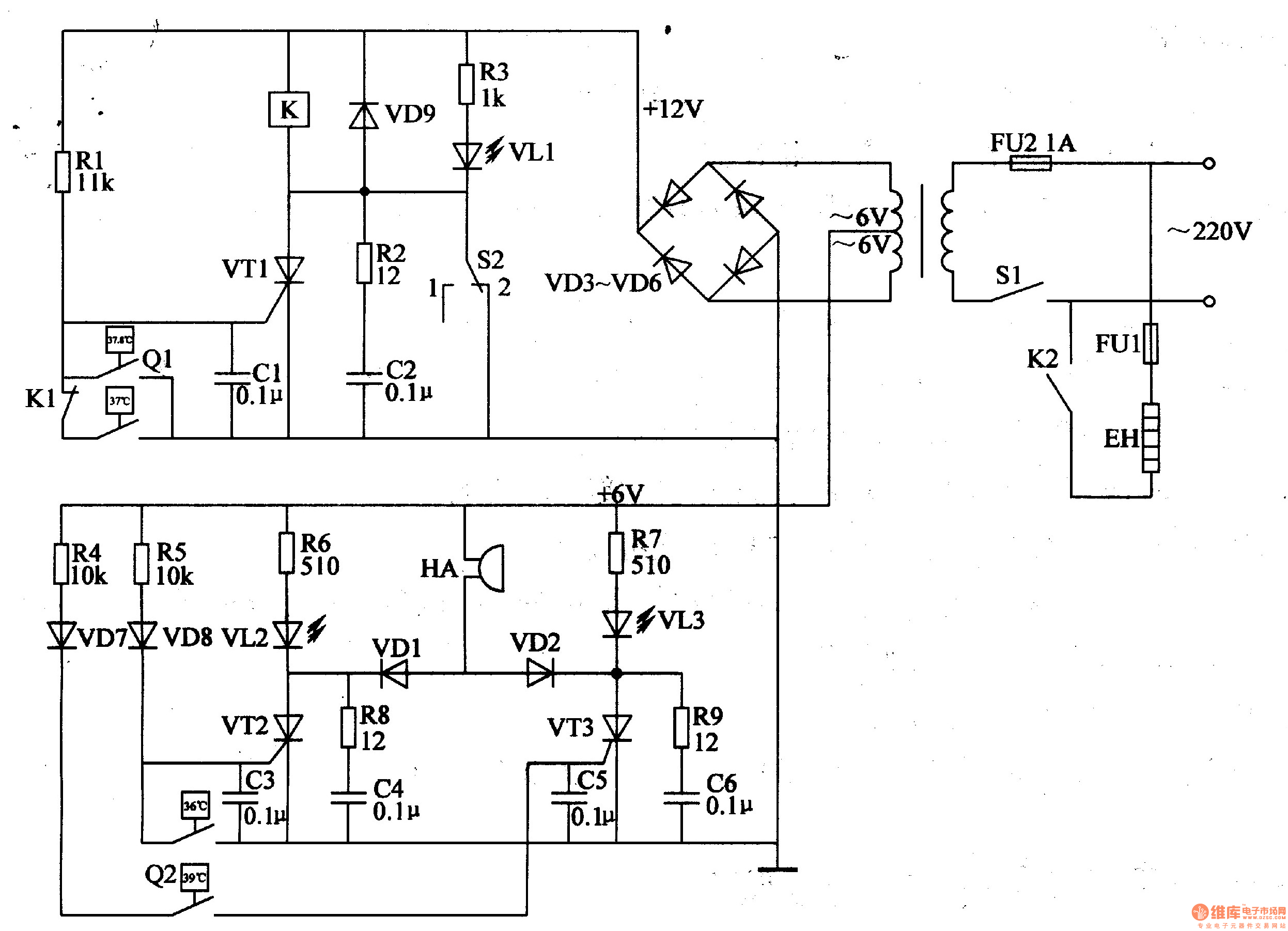
Eggs hatching incubator circuit diagram 4
The egg hatching incubator circuit comprises a power supply circuit, a constant temperature control circuit, and a sound and light alarm circuit, as illustrated in Figure 4-7. The power supply circuit includes a power switch (S1), a fuse (FU2), a...
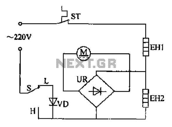
Comb electric circuit
The comb electric circuit illustrated in Figure 1-3 features two temperature settings. By toggling switch S to either the L or H position, different temperatures can be achieved. Once switch S is activated, the circuit powers the heating wires EH1...
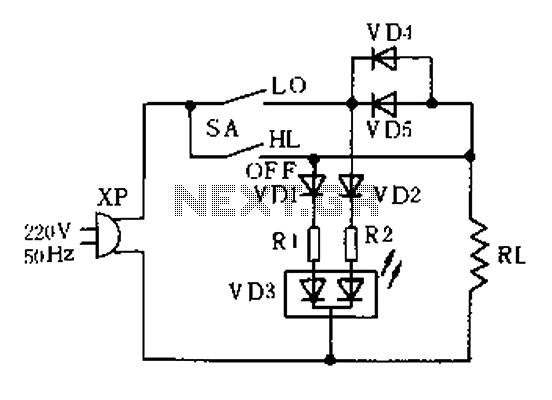
Electronic thermostat circuit
The thermostat electric circuit operates as depicted in the figure. It has three settings: off, low power (Lo), and high power (Peru HL). When the DIP switch SA is set to the Lo position, 220V AC is directed through diodes...