


Telephone control automatic lighting circuit 1
#telephone control
#automatic lighting
#delay circuit
#light triggering
#home automation
#energy saving
#night light
#telephone ringer
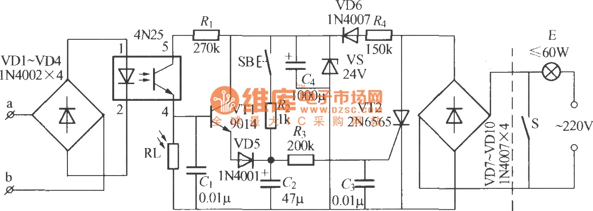
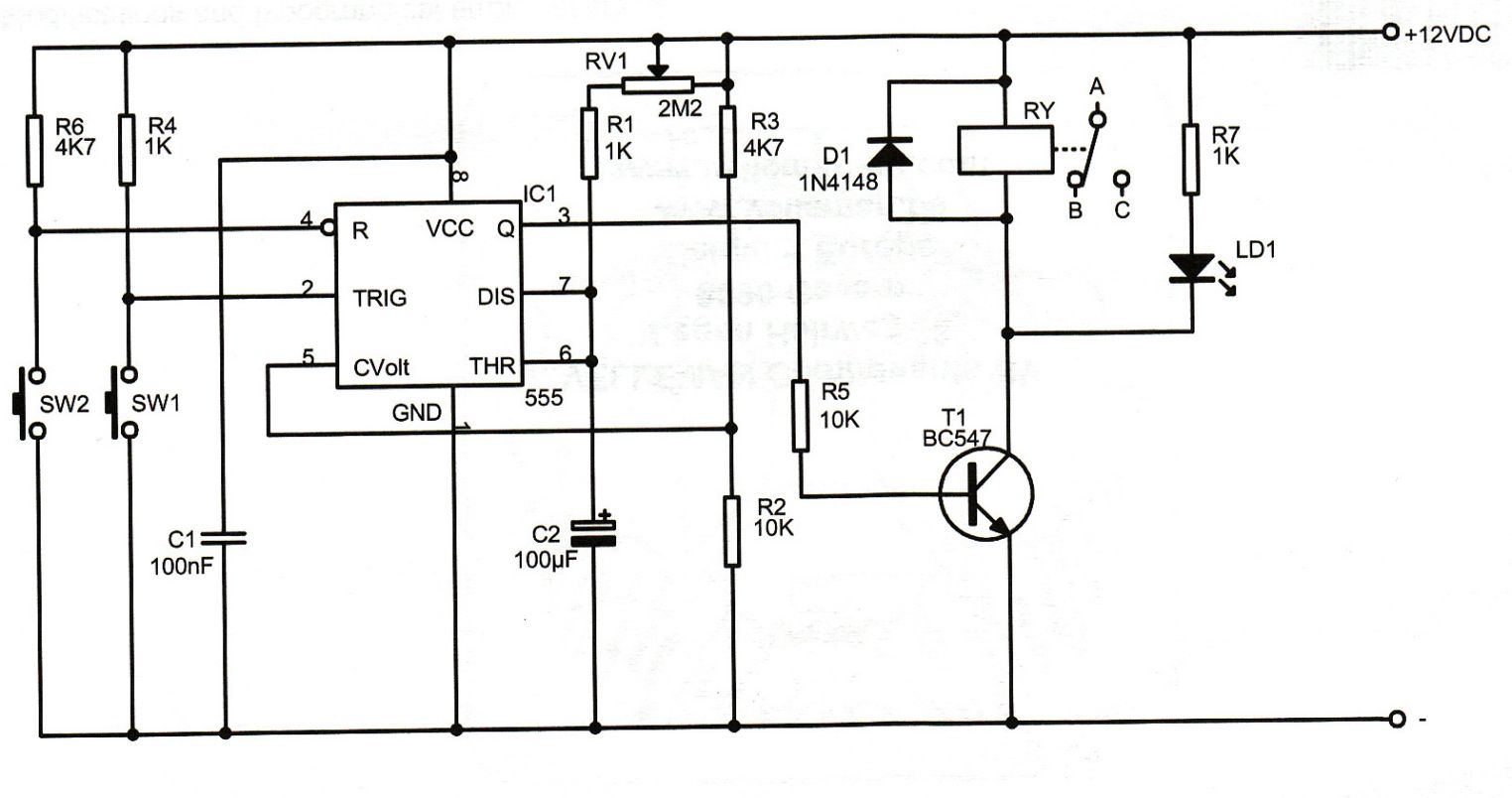
Description: The diagram illustrates an automatic lighting control circuit activated by a telephone. At night, when the telephone rings or the user picks up the receiver, the light turns on. If the telephone stops ringing (when no one is listening) or is placed on-hook, the light will remain on for a delay of 10 to 40 seconds before turning off automatically. Additionally, the circuit includes a manual light-triggering button, allowing the light to remain on for approximately 40 seconds when pressed.
The automatic lighting control circuit operates based on the principles of telephone line signaling. The circuit is designed to interface with the telephone system, detecting the ringing signal or the off-hook condition. A relay or transistor can be utilized to control the lighting load, ensuring that the light is activated when the telephone signals activity.
When the telephone rings, the circuit is triggered by the AC ringing voltage, which energizes a relay. This relay closure connects the light to the power supply, illuminating the light fixture. The duration of illumination is controlled by a timing circuit, which can be implemented using a simple RC (resistor-capacitor) delay timer or a microcontroller that can be programmed to provide the desired timing functionality.
In the case where the telephone stops ringing or is placed back on-hook, the timing circuit initiates a countdown that allows the light to remain on for a predetermined period (10 to 40 seconds) before automatically turning off. This feature ensures that the light does not remain on indefinitely, conserving energy when it is not needed.
The manual light-triggering button provides an additional method for activating the light without relying on the telephone's signaling. When pressed, this button temporarily bypasses the timing circuit, allowing the light to stay on for approximately 40 seconds. This feature is particularly useful in situations where immediate illumination is required without waiting for the telephone to ring.
Overall, this circuit design combines automatic and manual control mechanisms to provide efficient lighting solutions, particularly in environments where telephone activity is frequent during nighttime hours. Proper component selection, including relays, resistors, capacitors, and possibly a microcontroller, is essential for the reliable operation of this circuit.The diagram shows telephone control automatic lighting circuit. At night, when telephone rings or master takes up telephone transmitter dialing, the light can lighten; when telephone ringer stopped (no one listen) or on-hook, it can delay 10~40s, then the light can die out itself. Moreover, this circuit also set a light triggering button. The ligh t can lighten about 40s only by pressing the button.
The automatic lighting control circuit operates based on the principles of telephone line signaling. The circuit is designed to interface with the telephone system, detecting the ringing signal or the off-hook condition. A relay or transistor can be utilized to control the lighting load, ensuring that the light is activated when the telephone signals activity.
When the telephone rings, the circuit is triggered by the AC ringing voltage, which energizes a relay. This relay closure connects the light to the power supply, illuminating the light fixture. The duration of illumination is controlled by a timing circuit, which can be implemented using a simple RC (resistor-capacitor) delay timer or a microcontroller that can be programmed to provide the desired timing functionality.
In the case where the telephone stops ringing or is placed back on-hook, the timing circuit initiates a countdown that allows the light to remain on for a predetermined period (10 to 40 seconds) before automatically turning off. This feature ensures that the light does not remain on indefinitely, conserving energy when it is not needed.
The manual light-triggering button provides an additional method for activating the light without relying on the telephone's signaling. When pressed, this button temporarily bypasses the timing circuit, allowing the light to stay on for approximately 40 seconds. This feature is particularly useful in situations where immediate illumination is required without waiting for the telephone to ring.
Overall, this circuit design combines automatic and manual control mechanisms to provide efficient lighting solutions, particularly in environments where telephone activity is frequent during nighttime hours. Proper component selection, including relays, resistors, capacitors, and possibly a microcontroller, is essential for the reliable operation of this circuit.The diagram shows telephone control automatic lighting circuit. At night, when telephone rings or master takes up telephone transmitter dialing, the light can lighten; when telephone ringer stopped (no one listen) or on-hook, it can delay 10~40s, then the light can die out itself. Moreover, this circuit also set a light triggering button. The ligh t can lighten about 40s only by pressing the button.
Conducting pipe control rechargeable delay circuit
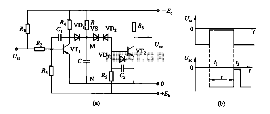
The circuit features a delay action with an instantaneous reset control mechanism. It is categorized into three types: a conducting pipe rechargeable delay circuit, a tube cut-off control rechargeable delay circuit, and a discharge-type delay circuit. In the conducting pipe...
Simple light delay circuit 3
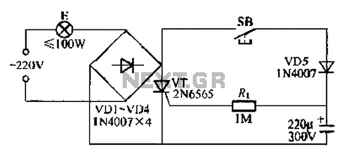
This circuit is a simple connection delay lamp circuit. When the lights are turned on and the switch is pressed, the power supply is activated. The capacitor charges rapidly, causing the thyristor (VT) to open, which in turn lights up...
Optional delay schematic division factor
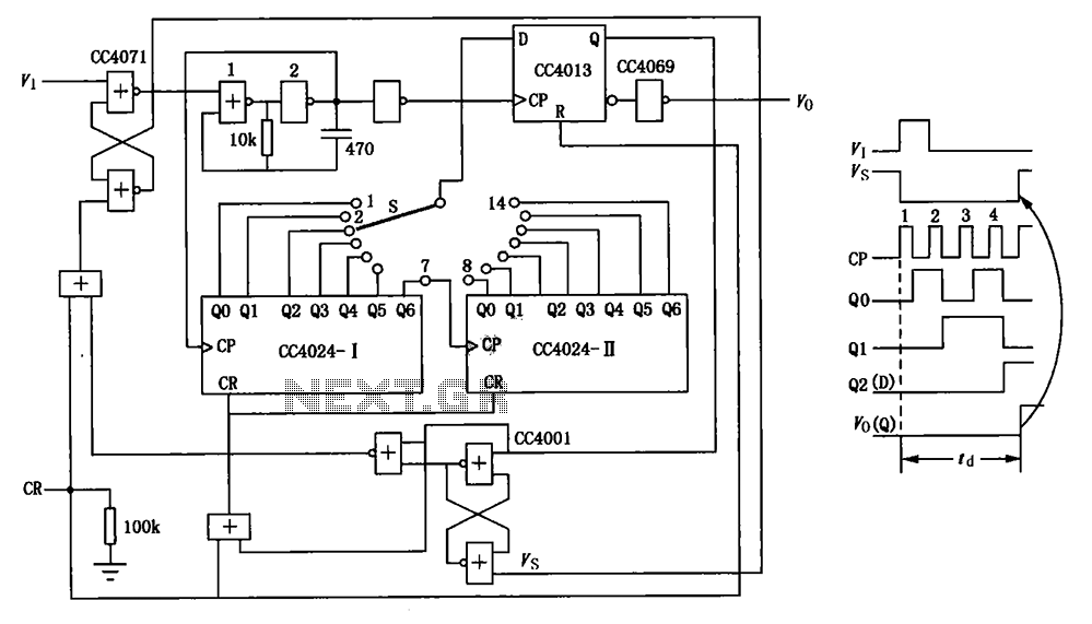
The circuit depicted in the figure is an optional delay circuit with a division factor. It consists of two 7-bit binary serial counters (CC4024) along with a controlled pulse source, which is composed of gate 1 and gate 2, as...
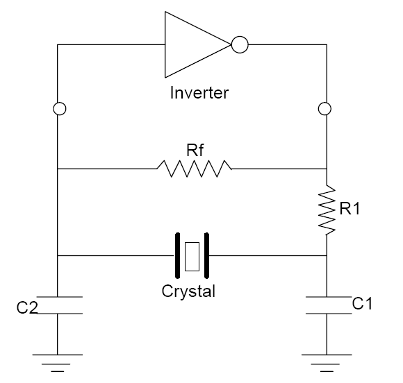
Delay Circuit
A small delay circuit is required to produce a pulse for a cell phone vibrational motor every 0.75 seconds, with an adjustable delay time ranging from 4 to 10 seconds. The circuit will be powered by a 9-volt battery.
To design...

A simple bedside lamp delay circuit
FIG IC, ICR, Ri, R, and AN composition form a bistable contact circuit with a Ge transistor. It includes components such as ICc, lc, c2, and Dj, and is associated with a one-shot delay circuit. The circuit can be enhanced...
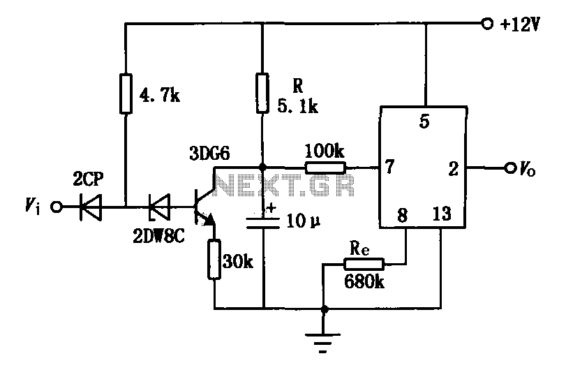
JEC-2 delay circuit diagram consisting of b
The delay application circuit is depicted in Figure JEC-2, which consists of two components. When the input transitions from logic level 0 to 1, the output also changes to 1 immediately. However, when the input transitions from high level 1...
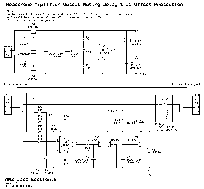
A muting delay & DC offset protection circuit
A low-pass filter is a stable state-space system that has an input and produces an output. If the input is a quasi-periodic signal, the output will be the same quasi-periodic signal with a phase shift. The key difference is that...
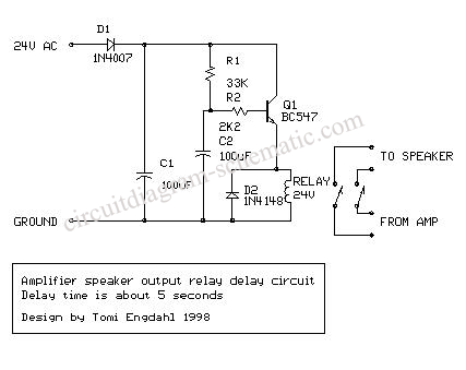
Circuit Delay and Speakers Protektor Using TL071
The circuit-delay relay for speakers serves as a delay mechanism that prevents the immediate activation of speakers when the amplifier is powered on. This feature is designed to protect the speakers from potential damage caused by sudden power surges. The...
12v 10 minute Off-Delay timer
An Xbox 360 console previously experienced a problem known as the 3 Red Lights of Death (3RLOD). To address this issue, the stock heatsinks were removed, and a Koolance external water cooling system was installed. This modification has effectively resolved...