


0-1V to 4-20 mA Converter
#current converter
#voltage converter
#TL062
#4-20mA
#signal conditioning
#PCB design
#dual supply
#attenuator
#protection resistor
#DC supply
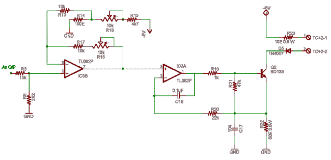
Description: Ensure a ±5V dual supply for the TL062 operational amplifier (IC3). The ground is shared as the power supply ground, allowing grounds to radiate from the ground plane on one side of the PCB. Resistors R3-R8 form an attenuator that may require design adjustments. Resistor R23 protects against shorting the 5V supply and can also connect to an unregulated or external supply of up to 24V DC, which is referenced to the circuit ground. Higher voltage allows for greater distance. Transistor Q2 acts as the current control device, while R22 (50Ω) serves as a shunt for current sampling. A 4-20mA output (with a suitable load connected) corresponds to a voltage range of 200mV to 1000mV across the 50Ω shunt. This voltage is fed into the closed-loop control system at the inverting pin of IC3a. If there is 1V at pin 3 and no current is flowing, pin 2 remains at 0V, causing the output to go positive and drive Q2. This results in a current flow until 1V builds across the shunt; if this voltage exceeds 1V, the output of the op-amp decreases, reducing the drive to the transistor and, consequently, the current. This process describes the voltage-to-current conversion with an open collector output. The next step involves converting the 0-2V signal to 0-1V using IC3B. Resistor R14 represents the 200mV offset set by the potentiometer R16. The operational amplifier IC3B functions as an analog computer, performing summation and subtraction to adjust the input and offset, achieving the desired voltage range from 200mV to 1000mV.
The circuit design focuses on providing a stable dual power supply of ±5V for the TL062 operational amplifier, ensuring that the ground connections are effectively managed to minimize noise and interference. The layout should emphasize a solid ground plane on one side of the printed circuit board (PCB), which helps in maintaining signal integrity and reducing potential ground loops.
The attenuation network formed by resistors R3 to R8 must be carefully calculated to meet the desired signal levels while ensuring that the operational amplifier operates within its linear range. The choice of R23 is critical for protecting the circuit from overvoltage conditions; it should be rated appropriately to handle potential surges without compromising the circuit's performance.
The current control mechanism is established through Q2, which regulates the output current based on feedback from the shunt resistor R22. The feedback loop is essential for maintaining the desired output current, particularly in applications that require precise current control, such as in sensor signal conditioning. The operational amplifier IC3a plays a pivotal role in this feedback loop, and its configuration should be optimized to ensure fast response times and stability.
In the subsequent stage, IC3B is employed to modify the output voltage range. The setting of R16 is crucial, as it determines the offset voltage that allows for the conversion from a 0-2V signal down to a 0-1V signal. The operational amplifier's configuration should be validated with simulations to ensure that the desired transfer function is achieved, and the output remains linear across the specified input range.
Overall, the design requires careful consideration of component values, layout strategies, and operational amplifier configurations to achieve a reliable and accurate signal processing circuit.Ensure 5/-5 dual supply for chip TL062 IC3. Gnd is common ps ground, let grounds radiate from ground plane in one side of PCB. R3-R8 is an attenuator that may need to be designed or modified. In output R23 is for protection from shorting of 5V supply, R23 can also go to an unregulated or external. supply upto 24V DC which is referenced to this cir cuits gnd. More voltage more distance. Q2 is the current control device, and R22 50E is the shunt for taking a sample of current. 4-20mA in the output (provided suitable load is connected) means 200mV- 1000mV across 50E shunt. This is fed to close loop control system of IC3a inverting pin. If there is 1V at pin 3 and no current is flowing pin 2 is at 0V so output goes positive and drives Q2. this results in a flow of current till a 1V builds across shunt, if it exceeds then output of opamp falls This reduces drive to transistor and hence current reduces.
That is the part of V to I conversion with open collector output. Now we need to convert 0-2 V to 0. 2 1. 0 V using IC3B. R14 is a representation of that 200mV offset set by R16 pot. the opamp IC3B adds both the input and this offset to get 200mV to 1000mV. for that the opamp IC3B is an analog computer, summer, subtracter. Try to now calculate the values for that. We aim to transmit more information by carrying articles. Please send us an E-mail to wanghuali@hqew. net within 15 days if we are involved in the problems of article content, copyright or other problems. We will delete it soon.
The circuit design focuses on providing a stable dual power supply of ±5V for the TL062 operational amplifier, ensuring that the ground connections are effectively managed to minimize noise and interference. The layout should emphasize a solid ground plane on one side of the printed circuit board (PCB), which helps in maintaining signal integrity and reducing potential ground loops.
The attenuation network formed by resistors R3 to R8 must be carefully calculated to meet the desired signal levels while ensuring that the operational amplifier operates within its linear range. The choice of R23 is critical for protecting the circuit from overvoltage conditions; it should be rated appropriately to handle potential surges without compromising the circuit's performance.
The current control mechanism is established through Q2, which regulates the output current based on feedback from the shunt resistor R22. The feedback loop is essential for maintaining the desired output current, particularly in applications that require precise current control, such as in sensor signal conditioning. The operational amplifier IC3a plays a pivotal role in this feedback loop, and its configuration should be optimized to ensure fast response times and stability.
In the subsequent stage, IC3B is employed to modify the output voltage range. The setting of R16 is crucial, as it determines the offset voltage that allows for the conversion from a 0-2V signal down to a 0-1V signal. The operational amplifier's configuration should be validated with simulations to ensure that the desired transfer function is achieved, and the output remains linear across the specified input range.
Overall, the design requires careful consideration of component values, layout strategies, and operational amplifier configurations to achieve a reliable and accurate signal processing circuit.Ensure 5/-5 dual supply for chip TL062 IC3. Gnd is common ps ground, let grounds radiate from ground plane in one side of PCB. R3-R8 is an attenuator that may need to be designed or modified. In output R23 is for protection from shorting of 5V supply, R23 can also go to an unregulated or external. supply upto 24V DC which is referenced to this cir cuits gnd. More voltage more distance. Q2 is the current control device, and R22 50E is the shunt for taking a sample of current. 4-20mA in the output (provided suitable load is connected) means 200mV- 1000mV across 50E shunt. This is fed to close loop control system of IC3a inverting pin. If there is 1V at pin 3 and no current is flowing pin 2 is at 0V so output goes positive and drives Q2. this results in a flow of current till a 1V builds across shunt, if it exceeds then output of opamp falls This reduces drive to transistor and hence current reduces.
That is the part of V to I conversion with open collector output. Now we need to convert 0-2 V to 0. 2 1. 0 V using IC3B. R14 is a representation of that 200mV offset set by R16 pot. the opamp IC3B adds both the input and this offset to get 200mV to 1000mV. for that the opamp IC3B is an analog computer, summer, subtracter. Try to now calculate the values for that. We aim to transmit more information by carrying articles. Please send us an E-mail to wanghuali@hqew. net within 15 days if we are involved in the problems of article content, copyright or other problems. We will delete it soon.
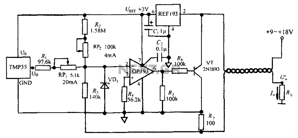
4 ~ 20mA transmitter circuit diagram TMP35 temperature
The circuit consists of a TMP35 temperature transmitter that converts a voltage signal output from the TMP35 into a standard 4 to 20 mA current signal. This configuration is suitable for use in automated instrumentation and industrial temperature control systems....
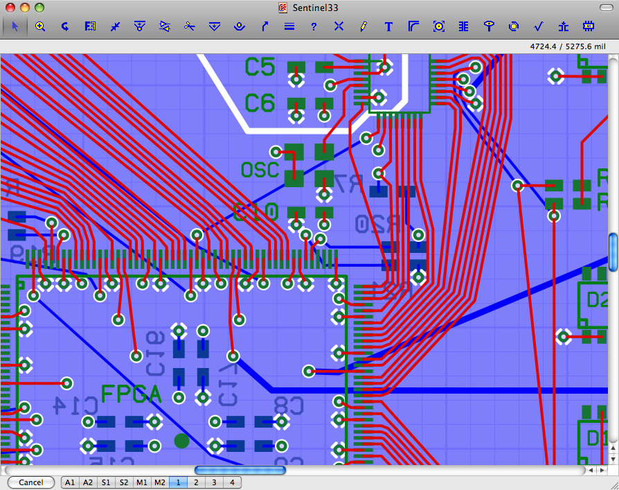
Osmond PCB
Osmond PCB is a flexible tool for designing printed circuit boards. It runs on Macintosh. Its many features include: * Virtually unlimited board sizes * Virtually unlimited number of board layers * Virtually unlimited number of parts.. More: * Spatial...
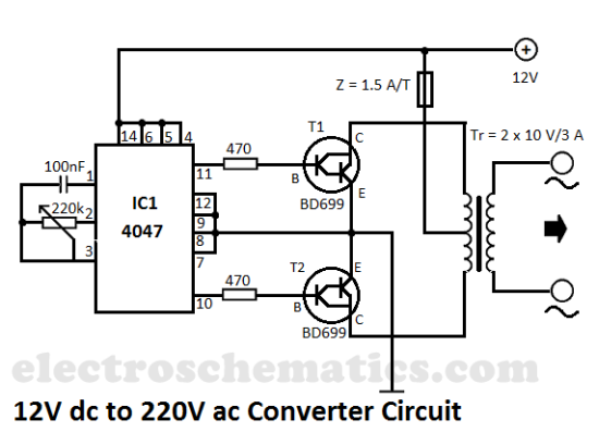
12V to 220V converter circuit
This DIY 12V to 220V voltage converter is built with a CMOS 4047, which serves as the main component for transforming 12V DC into 220V AC. The 4047 operates as an astable multivibrator, generating a symmetrical rectangular signal at pins...

Pulsonix PCB
Innovative yet easy-to-use PCB design editor. Includes many leading edge features for the casual and professional designer alike. Pulsonix contains a complete set of tools for designing Schematics and PCB designs in one integrated interface. Able to import many other...

Buck Boost Voltage Converter
In some cases, it is necessary to power a circuit from a battery, where the required supply voltage falls within the battery's discharge curve. A new battery provides a higher voltage than needed, while a battery nearing the end of...
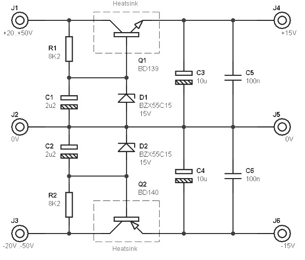
dual supply 15v based transistors
This circuit is designed to be integrated into an existing circuit, such as an audio amplifier, which already supplies symmetric voltages of +20V/-20V and +50V/-50V. The schematic diagram is derived from a dual polarity power supply circuit providing +/- 15V...
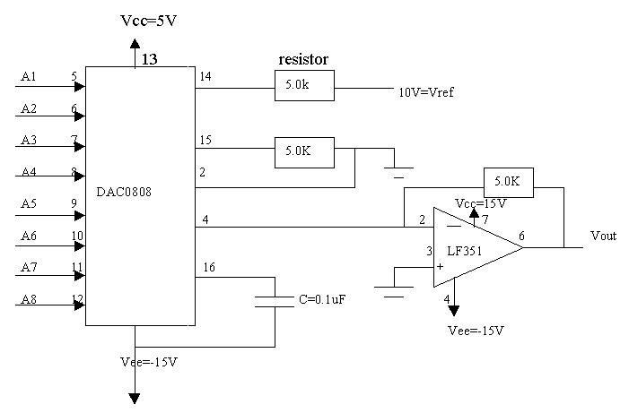
Signal Conditioners Information
Signal conditioning involves a series of operations applied to a signal to make it compatible for interfacing with other devices or systems. Signal conditioners are the devices that execute this operation, featuring both an input and an output. Typically, the...

Sprint-Layout
Design your own Printed Circuit Boards Sprint-Layout is a simple but powerful tool to create layouts for single-sided and double-sided PCBs (Printed Circuit Boards). More: The software comes along with all functions that are necessary for board design. Even professional...
EAGLE PCB Layout Editor
The EAGLE Layout Editor is an easy to use, yet powerful tool for designing printed circuit boards (PCBs). The name EAGLE is an acronym, which stands for: online Forward- and Back-Annotation, context-sensitive help function. More: no hardware copy protection! multiple...