


1000 watt power inverter schematic
#power inverter
#MOSFET
#1000 watt
#AC/DC
#high power
#FUSE protection
#RF50N06
#load requirement
#parallel MOSFET
#power circuit
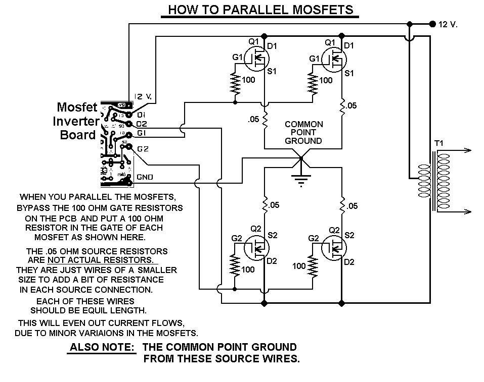
Description: This 1000-watt power inverter circuit diagram utilizes the MOSFET RF50N06. To achieve higher power output, additional MOSFETs can be connected in parallel with the RF50N06. These MOSFETs are rated for 60 volts and 50 amps. It is essential to include a fuse in the power line, and a load must always be connected while power is applied. The output power of this inverter can reach up to 1 kW, depending on the output power transformer used. Custom transformers may be employed for experimentation to achieve optimal results.
The 1000-watt power inverter circuit is designed to convert DC voltage into AC voltage, making it suitable for powering various electronic devices. The core component, the RF50N06 MOSFET, features a robust rating of 60 volts and 50 amps, allowing it to handle substantial power levels efficiently. When higher output is required, additional RF50N06 MOSFETs can be paralleled to increase the overall current capacity, ensuring that the inverter can meet the demands of more power-intensive loads.
In the schematic, the MOSFETs are typically arranged in a half-bridge or full-bridge configuration, which is essential for generating the desired AC waveform. The gate drive circuitry must be carefully designed to switch the MOSFETs on and off at the appropriate frequency, commonly in the range of several kilohertz, to produce a stable output waveform. A pulse-width modulation (PWM) technique may be employed to control the output voltage and frequency, providing versatility for different applications.
Incorporating a fuse in the power line is a critical safety measure. It protects the circuit from overcurrent situations that could lead to component failure or fire hazards. The fuse should be rated appropriately for the maximum expected current to ensure reliable operation while safeguarding the circuit.
The output transformer plays a vital role in this inverter circuit. It steps up the voltage to the desired level for AC applications. The choice of transformer affects the efficiency and performance of the inverter, and experimenting with different transformer designs can yield improved results. Users are encouraged to explore custom transformer configurations to optimize power output and efficiency based on their specific needs.
Overall, this power inverter circuit is a versatile solution for converting DC power into AC power, suitable for a wide range of applications, from small electronic devices to larger appliances, depending on the transformer and load configuration used.This 1000 watt power inverter circuit diagram based on MOSFET RF50N06. If you want more power then add additional MOSFET paralleled at RF50N06. This MOSFETS are 60 Volts and 50 Amps as rated. It is necessary to connect a FUSE with the power line and always a LOAD have to connected while power is being applied. The output power of this inverter is u p-to 1k watt, it depends on output power transformer. You can use your custom transformer with experimenting for best result.
The 1000-watt power inverter circuit is designed to convert DC voltage into AC voltage, making it suitable for powering various electronic devices. The core component, the RF50N06 MOSFET, features a robust rating of 60 volts and 50 amps, allowing it to handle substantial power levels efficiently. When higher output is required, additional RF50N06 MOSFETs can be paralleled to increase the overall current capacity, ensuring that the inverter can meet the demands of more power-intensive loads.
In the schematic, the MOSFETs are typically arranged in a half-bridge or full-bridge configuration, which is essential for generating the desired AC waveform. The gate drive circuitry must be carefully designed to switch the MOSFETs on and off at the appropriate frequency, commonly in the range of several kilohertz, to produce a stable output waveform. A pulse-width modulation (PWM) technique may be employed to control the output voltage and frequency, providing versatility for different applications.
Incorporating a fuse in the power line is a critical safety measure. It protects the circuit from overcurrent situations that could lead to component failure or fire hazards. The fuse should be rated appropriately for the maximum expected current to ensure reliable operation while safeguarding the circuit.
The output transformer plays a vital role in this inverter circuit. It steps up the voltage to the desired level for AC applications. The choice of transformer affects the efficiency and performance of the inverter, and experimenting with different transformer designs can yield improved results. Users are encouraged to explore custom transformer configurations to optimize power output and efficiency based on their specific needs.
Overall, this power inverter circuit is a versatile solution for converting DC power into AC power, suitable for a wide range of applications, from small electronic devices to larger appliances, depending on the transformer and load configuration used.This 1000 watt power inverter circuit diagram based on MOSFET RF50N06. If you want more power then add additional MOSFET paralleled at RF50N06. This MOSFETS are 60 Volts and 50 Amps as rated. It is necessary to connect a FUSE with the power line and always a LOAD have to connected while power is being applied. The output power of this inverter is u p-to 1k watt, it depends on output power transformer. You can use your custom transformer with experimenting for best result.
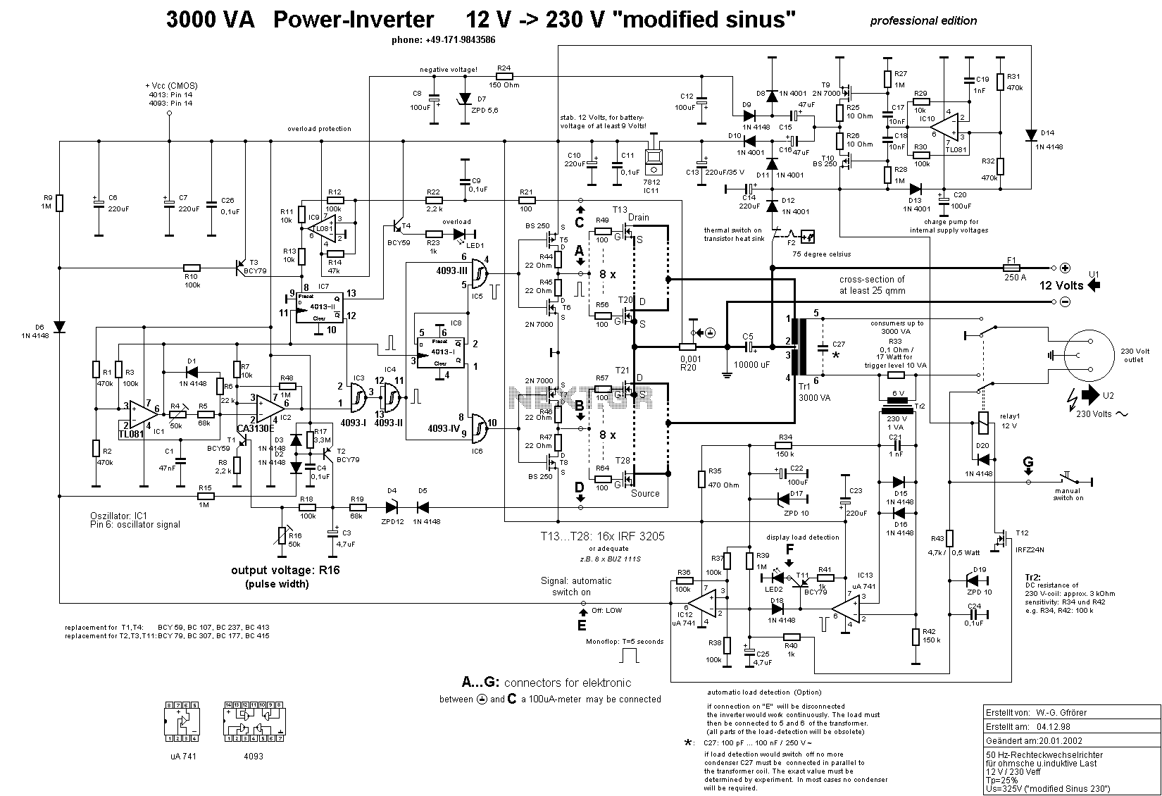
3000 Watt Inverter
This is a high-power inverter circuit designed to deliver an AC power output of 3000W. It converts 12 Volt DC battery voltage into a square wave voltage with a frequency of 50 Hz and a duty cycle of 25%.
The inverter...
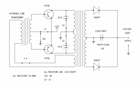
inverter to change dc current to ac
Afshin Izadian at Indiana University has developed a new power inverter that utilizes a single switching transistor and is capable of generating infinite-level voltages.
The power inverter designed by Afshin Izadian represents a significant advancement in the field of power electronics....
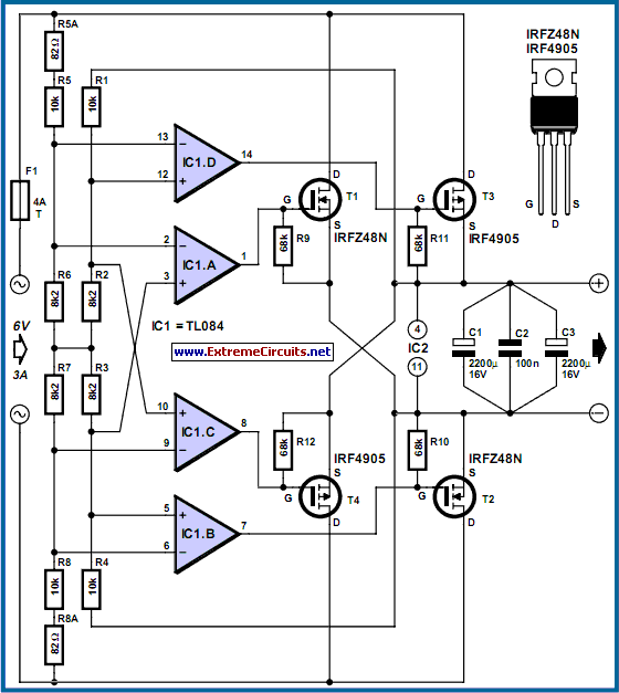
Power MOSFET Bridge Rectifier
The losses in a bridge rectifier can become significant when rectifying low voltages. The voltage drop across the bridge is approximately 1.5 V, which constitutes about 25% loss with an input voltage of 6V. This loss can be reduced by...
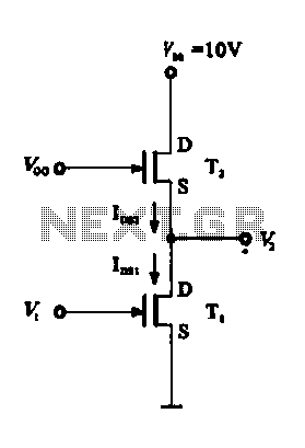
MOS FET inverter
A Field Effect Transistor (FET) can function as a linear amplifier, and it can also be utilized to create a logic gate circuit.
FETs are semiconductor devices that control the flow of current using an electric field. Due to their high...
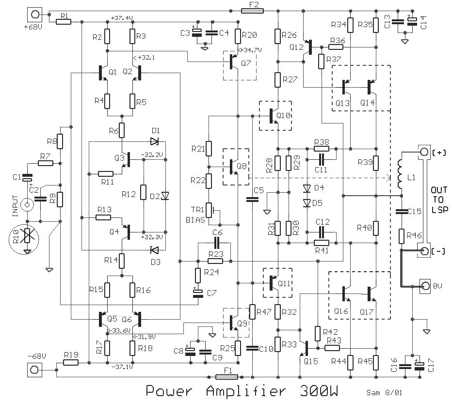
high power amplifier 300w circuit
There is no substitute for sheer power—low-efficiency speakers, outdoor sound systems, or perhaps the full dynamic range of a high-power amplifier. Whatever the requirement, this super power module should meet the needs. The amplifier can be divided into three distinct...
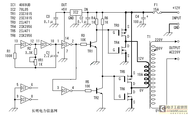
Make circuit of the inverter and operating principle by oneself
An inverter is introduced which primarily utilizes a MOS field-effect transistor in conjunction with a conventional power transformer. The output power of the inverter is determined by the specifications of both the MOS field-effect transistor and the transformer, thereby eliminating...
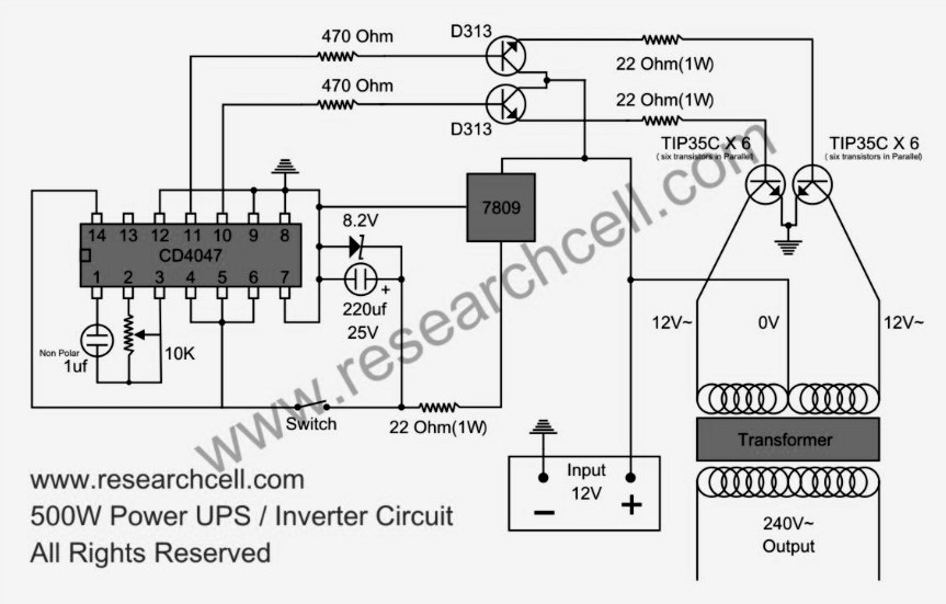
500w power inverter circuit diagram based tip35c
This circuit diagram features a single variable resistor utilized to adjust the frequency of a 240V AC output current. It is advisable to use a frequency meter to modify the frequency from 50Hz to 60Hz according to specific requirements. It...
.jpg "mosfet prevents battery damage circuit")
mosfet prevents battery damage
Sealed lead-acid batteries are commonly used in power electronics applications, including uninterruptible power supplies (UPS), inverters, and emergency lamps. They provide power to the load when utility power is unavailable. Upon restoration of utility power, a charger supplies power to...
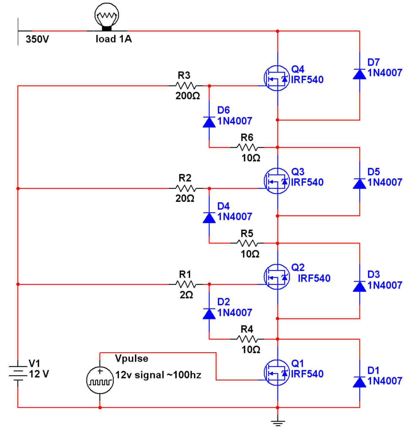
MOSFETs IN SERIES
Some time ago, a document was encountered that explains how to wire MOSFETs in series to achieve higher voltages (pages 10-14). This is the only schematic found to be functional so far. However, an issue arises when attempting to add...