


12-Vdc-battery-operated-120-vac-power-source
#battery-operated
#transformer
#square wave
#60 Hz
#self-starting
#20 W
#power source
#120 VAC
#12 VDC
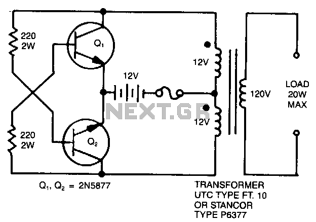
Description: A simple 120 V to 24 V center-tapped control transformer, along with four additional components, can accomplish the task. This circuit produces a clean 200 V peak-to-peak square wave at 60 Hz and is capable of supplying up to 20 W. The circuit operates in a self-starting and free-running mode. If transistor Q1 has a faster response time and higher gain than transistor Q2, it will turn on first when input power is applied, keeping Q2 off. The load current and transformer magnetizing current then flow through the upper half of the primary winding, and the auto transformer action provides the necessary base drive until the transformer reaches saturation. Once saturation occurs, Q1 loses its base drive.
As Q1 turns off, the transformer voltages reverse, activating Q2 and repeating the cycle. The output frequency is influenced by the transformer core material and the input voltage, remaining largely unaffected by the load. Typically, the frequency will range from 50 to 60 Hz when utilizing a 60 Hz transformer in conjunction with a car battery or equivalent power source. The output voltage is determined by the turns ratio and the difference between the input voltage and the saturation voltage of the transistors. For applications requiring higher power, larger transformers and transistors should be utilized. This type of inverter is commonly employed in radios, phonographs, hand tools, shavers, and small fluorescent lamps. However, it is not suitable for reactive loads (such as motors) or loads with high inrush currents, including coffee pots, frying pans, and heaters.
The circuit design employs a center-tapped transformer which plays a crucial role in generating the required square wave output. The transformer is configured to step down the input voltage from 120 V to 24 V, allowing for efficient operation within the specified power range. The inclusion of transistors Q1 and Q2 in a push-pull configuration enables the inverter to alternate the conduction between the two devices, effectively creating the square wave output.
The self-starting feature of the inverter is essential for reliable operation, ensuring that the circuit can initiate without external triggering mechanisms. The feedback loop created by the transformer’s auto transformer action is vital, as it provides base drive to Q1 until saturation is reached. This saturation condition is a critical point in the operation, as it facilitates the transition to Q2, allowing for continuous oscillation and stable output.
The output waveform is characterized by its peak-to-peak voltage, which is a function of the transformer turns ratio and the applied input voltage. The design must consider the saturation characteristics of the transistors to ensure that the output remains within operational limits. Additionally, the inverter's inability to handle reactive loads must be taken into account during application, as this could lead to circuit failure or inefficiency.
In practical applications, the choice of components, particularly the transformer and transistors, should align with the desired output specifications. Larger transformers and transistors can enhance performance and reliability for higher power applications. The circuit's simplicity makes it an attractive solution for low-power devices, while its limitations should guide the selection of appropriate use cases.A simple 120 V: 24 V, center-tapped control transformer and four additional components can do the job. This circuit outputs a clean 200 V pk-pk square wave at 60 Hz and can supply up to 20 W. The circuit is self-starting and free-running. If Q1 is faster and has a higher gain than Q2, it will tum on first when you apply the input power and will hold Q2 off.
Load current and transformer magnetizing current then flows in the upper half of the primary winding, and auto transformer action supplies the base drive until the transformer saturates. When that action occurs, Q1 loses its base drive. As it turns off, the transformer voltages reverse, turning Q2 on and repeating the cycle. The output frequency depends on the transformer iron and input voltage, but not on the load. The frequency will generally range between 50 to 60 Hz with a 60-Hz transformer and car battery or equivalent source. The output voltage depends on turns ratio and the difference between input voltage and transistor saturation voltage.
For higher power, use larger transformers and transistors. This type of inverter normally is used in radios, phonographs, hand tools, shavers, and small fluorescent lamps. It will not work with reactive loads (motors) or loads with high inrush currents, such as coffee pots, frying pans, and heaters.
As Q1 turns off, the transformer voltages reverse, activating Q2 and repeating the cycle. The output frequency is influenced by the transformer core material and the input voltage, remaining largely unaffected by the load. Typically, the frequency will range from 50 to 60 Hz when utilizing a 60 Hz transformer in conjunction with a car battery or equivalent power source. The output voltage is determined by the turns ratio and the difference between the input voltage and the saturation voltage of the transistors. For applications requiring higher power, larger transformers and transistors should be utilized. This type of inverter is commonly employed in radios, phonographs, hand tools, shavers, and small fluorescent lamps. However, it is not suitable for reactive loads (such as motors) or loads with high inrush currents, including coffee pots, frying pans, and heaters.
The circuit design employs a center-tapped transformer which plays a crucial role in generating the required square wave output. The transformer is configured to step down the input voltage from 120 V to 24 V, allowing for efficient operation within the specified power range. The inclusion of transistors Q1 and Q2 in a push-pull configuration enables the inverter to alternate the conduction between the two devices, effectively creating the square wave output.
The self-starting feature of the inverter is essential for reliable operation, ensuring that the circuit can initiate without external triggering mechanisms. The feedback loop created by the transformer’s auto transformer action is vital, as it provides base drive to Q1 until saturation is reached. This saturation condition is a critical point in the operation, as it facilitates the transition to Q2, allowing for continuous oscillation and stable output.
The output waveform is characterized by its peak-to-peak voltage, which is a function of the transformer turns ratio and the applied input voltage. The design must consider the saturation characteristics of the transistors to ensure that the output remains within operational limits. Additionally, the inverter's inability to handle reactive loads must be taken into account during application, as this could lead to circuit failure or inefficiency.
In practical applications, the choice of components, particularly the transformer and transistors, should align with the desired output specifications. Larger transformers and transistors can enhance performance and reliability for higher power applications. The circuit's simplicity makes it an attractive solution for low-power devices, while its limitations should guide the selection of appropriate use cases.A simple 120 V: 24 V, center-tapped control transformer and four additional components can do the job. This circuit outputs a clean 200 V pk-pk square wave at 60 Hz and can supply up to 20 W. The circuit is self-starting and free-running. If Q1 is faster and has a higher gain than Q2, it will tum on first when you apply the input power and will hold Q2 off.
Load current and transformer magnetizing current then flows in the upper half of the primary winding, and auto transformer action supplies the base drive until the transformer saturates. When that action occurs, Q1 loses its base drive. As it turns off, the transformer voltages reverse, turning Q2 on and repeating the cycle. The output frequency depends on the transformer iron and input voltage, but not on the load. The frequency will generally range between 50 to 60 Hz with a 60-Hz transformer and car battery or equivalent source. The output voltage depends on turns ratio and the difference between input voltage and transistor saturation voltage.
For higher power, use larger transformers and transistors. This type of inverter normally is used in radios, phonographs, hand tools, shavers, and small fluorescent lamps. It will not work with reactive loads (motors) or loads with high inrush currents, such as coffee pots, frying pans, and heaters.
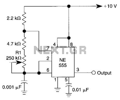
Variable Square Wave Generator Circuit
This simple square-wave generator produces a variable frequency output ranging from 2800 Hz to 80 kHz, as indicated by the specified values. The frequency can be adjusted using potentiometer R1.
The square-wave generator circuit typically employs a combination of resistors, capacitors,...
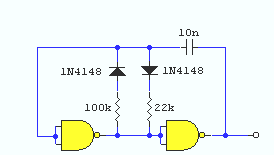
square wave oscillator circuit
A simple square wave oscillator can be created using two gates from a CMOS 4011 NAND chip. Alternatively, a CMOS 4001 chip or a TTL equivalent can also be utilized. In this circuit, the mark-space ratio can be independently controlled...
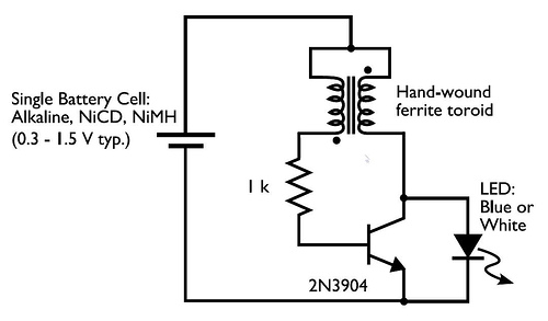
transformer Low voltage oscillator for joule thief
A transformer with two input leads and three output leads was used. An LED was connected to two of the output leads, and when a dead AA battery was connected to the input leads, the LED blinked for a brief...
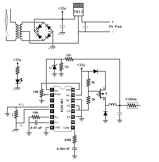
kermit
The neighbor's drill charger ceased functioning, and it was discovered that the primary wires in the transformer were defective. The charger featured a straightforward design, comprising a transformer, a diode bridge, and a larger resistor. It was rated to deliver...
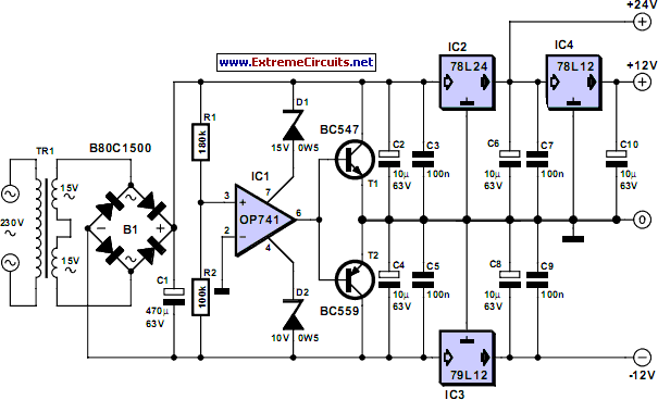
Triple Power Supply
Inexpensive miniature transformers typically provide one or two secondary voltages, which are sufficient for generating a set of positive and negative supply voltages, as required for operational amplifier circuits. However, if an additional voltage higher than either of the supply...
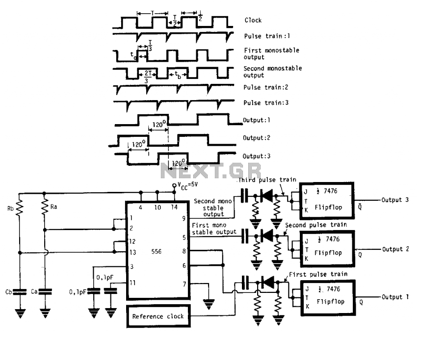
3 square waves generator
The circuit generates three square wave outputs with a 120° phase difference between each output. The reference clock frequency is set to twice the desired output frequency. This can be achieved using a crystal oscillator followed by a series of...
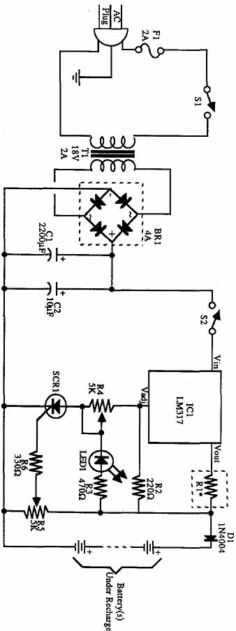
Build an Experimenters Power Supply
The incoming AC is routed to the primary terminals of a 12.6-volt transformer. The hot side of the AC is connected through a fuse and a single-pole single-throw (SPST) toggle switch. When the switch is in the OFF position, the...
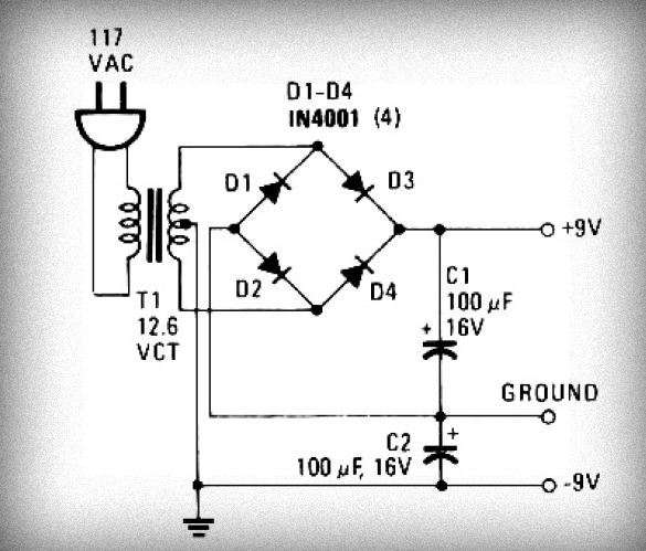
Simple Power Supply Circuit easy to make Schematic Diagram
Initially, voltage from AC 220V or 110V enters the transformer, which reduces it to 12V AC. This AC voltage is then rectified using either four diodes or a bridge rectifier to convert it to DC voltage. The resulting DC voltage...
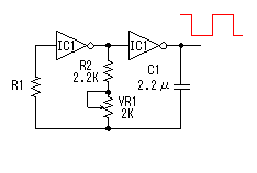
Circuit explanation of DC/AC inverter
This circuit is a square wave oscillator that utilizes CMOS-type logic inverters. The term "logic inverter" is used to prevent confusion with a DC/AC inverter. The oscillator's output is connected to a drive circuit via the logic inverters. The antiphase...