


12vac to 220vac inverter circuit
#555 timer
#oscillator
#transformer
#DC to AC
#power inverter
#step-up
#low-frequency
#filament transformer
#frequency tuning
#12V to 220V
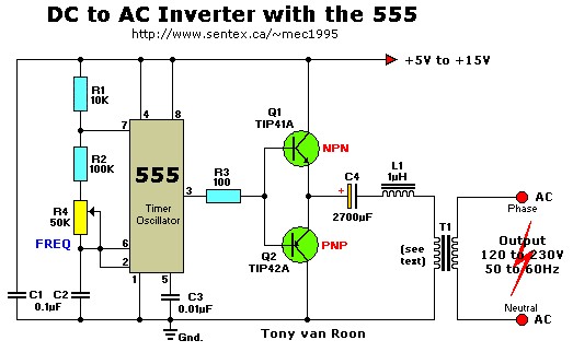
Description: This simple 12V DC to 220V AC inverter circuit generates an AC output at line frequency and voltage. The 555 timer is configured as a low-frequency oscillator, adjustable over the frequency range of 50 to 60 Hz via the frequency potentiometer R4. The output from the 555 timer is amplified by transistors Q1 and Q2, which then drives transformer T1, a reverse-connected filament transformer with the appropriate step-up turns ratio. Additionally, capacitor C4 and coil L1 filter the input to T1, ensuring that the output is effectively a sine wave. The value of transformer T1 should be adjusted according to the desired output voltage.
This inverter circuit utilizes a 555 timer IC in astable mode to produce a square wave signal, which is essential for driving the power transistors Q1 and Q2. The frequency adjustment through potentiometer R4 allows for fine-tuning of the output frequency, which is critical for applications requiring precise line frequency operation.
Transistors Q1 and Q2 serve as the amplification stage, switching the current through the primary winding of transformer T1. The transformer is configured such that its secondary winding provides the necessary voltage increase from 12V DC to 220V AC. The choice of transformer is crucial; a filament transformer is typically used due to its ability to handle the necessary power levels and provide the required turns ratio for voltage step-up.
Capacitor C4 and inductor L1 form a low-pass filter that smooths the output waveform. This filtering is vital to convert the square wave output from the transistors into a more sinusoidal waveform, which is generally required for most AC applications. The filter helps to reduce harmonic distortion, improving the quality of the AC output.
Careful selection of component values, particularly for the transformer and filter components, is essential for optimal performance of the inverter. The circuit design must ensure that the transformer can handle the expected load, and the filter components must be chosen to achieve the desired output characteristics while maintaining efficiency. This inverter circuit can be employed in various applications, including powering small appliances or serving as a backup power source.This simple 12VDC to 220VAC inverter circuit produces an AC output at line frequency and voltage. The 555 is configured as a low-frequency oscillator, tunable over the frequency range of 50 to 60 Hz by Frequency potentiometer R4. The 555 feeds its output (amplified by Q1 and Q2) to the input of transformerT1, a reverse-connected filament transformer with the necessary step-up turns ratio.
Capacitor C4 and coil L1 filter the input to T1, assuring that it is effectively a sine wave. Adjust the value of T1 to your voltage.
This inverter circuit utilizes a 555 timer IC in astable mode to produce a square wave signal, which is essential for driving the power transistors Q1 and Q2. The frequency adjustment through potentiometer R4 allows for fine-tuning of the output frequency, which is critical for applications requiring precise line frequency operation.
Transistors Q1 and Q2 serve as the amplification stage, switching the current through the primary winding of transformer T1. The transformer is configured such that its secondary winding provides the necessary voltage increase from 12V DC to 220V AC. The choice of transformer is crucial; a filament transformer is typically used due to its ability to handle the necessary power levels and provide the required turns ratio for voltage step-up.
Capacitor C4 and inductor L1 form a low-pass filter that smooths the output waveform. This filtering is vital to convert the square wave output from the transistors into a more sinusoidal waveform, which is generally required for most AC applications. The filter helps to reduce harmonic distortion, improving the quality of the AC output.
Careful selection of component values, particularly for the transformer and filter components, is essential for optimal performance of the inverter. The circuit design must ensure that the transformer can handle the expected load, and the filter components must be chosen to achieve the desired output characteristics while maintaining efficiency. This inverter circuit can be employed in various applications, including powering small appliances or serving as a backup power source.This simple 12VDC to 220VAC inverter circuit produces an AC output at line frequency and voltage. The 555 is configured as a low-frequency oscillator, tunable over the frequency range of 50 to 60 Hz by Frequency potentiometer R4. The 555 feeds its output (amplified by Q1 and Q2) to the input of transformerT1, a reverse-connected filament transformer with the necessary step-up turns ratio.
Capacitor C4 and coil L1 filter the input to T1, assuring that it is effectively a sine wave. Adjust the value of T1 to your voltage.

Water Activated Sensor Alarm Using 555 PCB
The circuit utilizes a 555 integrated circuit (IC) functioning as an astable multivibrator. When a positive 9 volts is applied to pin 8, the circuit generates sound through a speaker. The connection to pin 8 is routed through a transistor,...
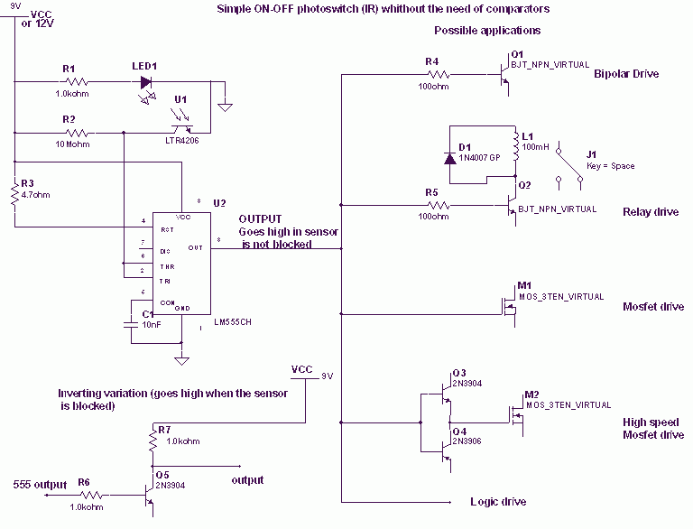
Optical switch detector with 555
When the phototransistor is struck by IR light, it conducts, and the voltage between the 1 MΩ resistor (arbitrary) and the phototransistor drops from VCC to lower values. When the voltage drops lower than VCC/3, the 555 is triggered and...
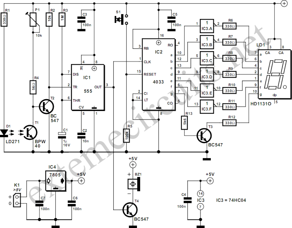
Light Gate With Counter Using 555 And 4033
The circuit described here counts the number of times an infrared beam is interrupted. It can be utilized to count the number of individuals entering a room or to track how often an object, such as a ball, passes through...
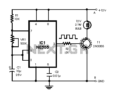
Brakelight Flasher PCB
This is essentially a flasher circuit modified to control a bulb instead of an LED. It utilizes a 555 timer integrated circuit functioning as an astable multivibrator. The flashing rate can be adjusted from very fast to a maximum of...
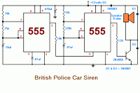
Latest British Police Car Siren circuit
The 555 timer on the right is configured as an alarm sound generator, while the second 555 timer on the left operates as a 1 Hz astable multivibrator. The output from the left timer modulates the frequency of the right...
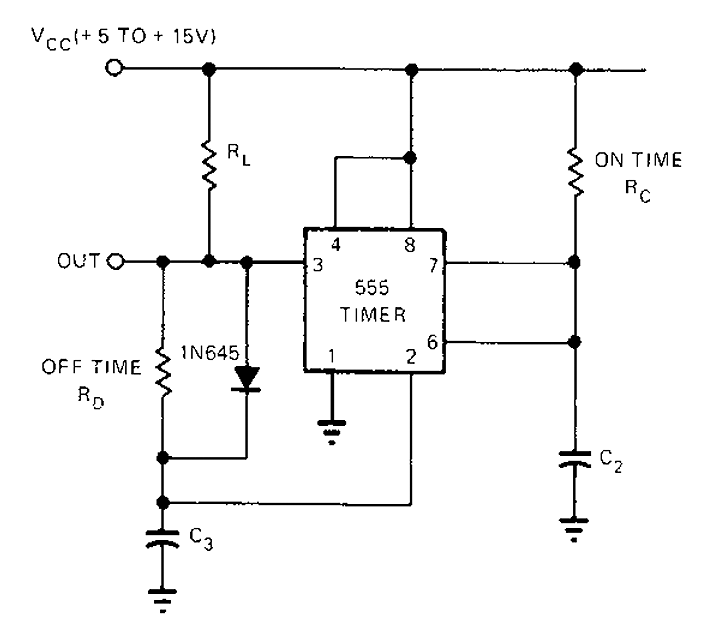
555 Timer astable oscillator circuit
The 555 timer circuit has unsteady open and closing times that are independent of one another. One time constant is given by 1.1RcC2, while another time constant is defined as 1.1RcC3. The free-running period is the sum of these time...
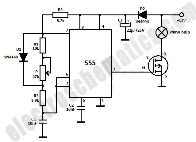
Dim Light Bulbs with 555 IC Circuit
This light dimmer is designed to adjust the brightness of 12V light bulbs utilizing the widely recognized 555 timer, which is configured as an astable multivibrator. The pulses generated by the timer control the power delivered to the light bulbs,...
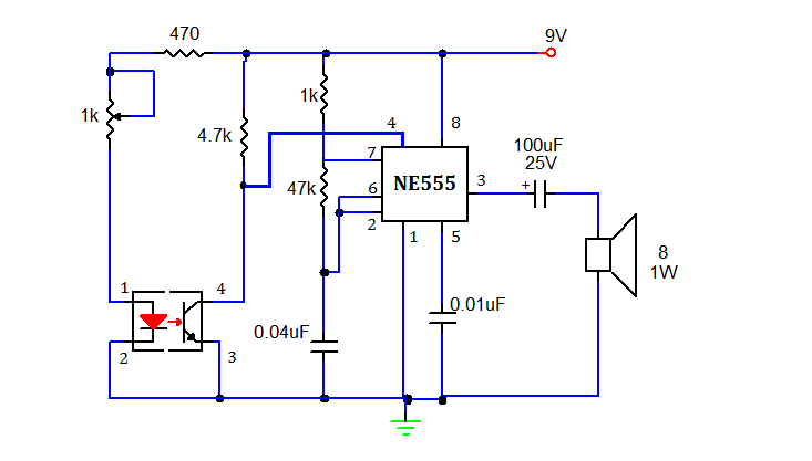
SMOKE DETECTOR USING 555 TIMER
This document presents a simple smoke sensing alarm circuit utilizing a 555 timer. The circuit is designed to detect smoke and trigger an alarm when the air is contaminated. The components employed in this design include an astable multivibrator and...
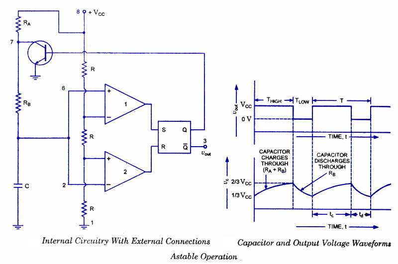
555 Timer as an Astable Multivibrator
An astable multivibrator, often referred to as a free-running multivibrator, is a rectangular-wave generating circuit. Unlike the monostable multivibrator, this circuit does not require any external trigger to change the state of the output, hence the term free-running. Before constructing...