


555 timer IC Inverter circuit schematic 12V to 220V
#555 timer
#DC to AC
#inverter
#12V to 220V
#power conversion
#emergency power
#low cost
#circuit diagram
#electronics project
#DIY
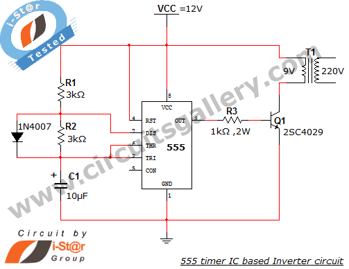
Description: This article explains what an inverter is and how to construct a simple, low-cost 12V to 220V inverter circuit. An inverter functions as a DC to AC converter and is a valuable electronic product for compensating for emergency power failures by performing DC to AC conversion. The provided inverter circuit diagram utilizes a 555 timer IC in astable multivibrator mode to generate AC oscillations. These oscillations are switched through the transistor 2SC4029 to a transformer, which steps up the voltage to 220V AC. A 12V battery and a battery charger circuit are recommended for this project. The design of the inverter circuit is also included. The output pulse from the 555 astable multivibrator is fed to the base of the power transistor 2N5192, which operates as a switch, allowing the 12V DC supply to pass through the transformer at a frequency of 50 Hz.
The inverter circuit described operates on the principle of converting direct current (DC) from a 12V source into alternating current (AC) at a voltage level of 220V. The core component, the 555 timer IC, is configured in astable mode, which generates a continuous square wave output. This output is essential for creating the necessary AC waveform.
In the circuit, the 555 timer's output is connected to the base of the transistor 2N5192, which acts as a switch. When the 555 timer outputs a high signal, the transistor conducts, allowing current to flow from the 12V battery through the primary winding of the transformer. The transformer is crucial as it steps up the voltage from 12V to 220V, suitable for typical household electrical devices.
The transistor 2SC4029 plays a role in managing the oscillations produced by the 555 timer and ensuring that the signal is appropriately amplified before reaching the transformer. This transistor is selected for its capability to handle the power levels involved in the circuit.
The output frequency of the inverter is set at approximately 50 Hz, which is standard for AC power in many regions. This frequency is determined by the timing components connected to the 555 timer, specifically the resistors and capacitors that set the charging and discharging times.
Overall, the described inverter circuit is a practical solution for converting low-voltage DC power into high-voltage AC power, making it suitable for applications where backup power is necessary. The inclusion of a battery charger circuit ensures that the 12V battery remains charged and ready for use when needed. This simple yet effective design can be implemented with readily available components, making it accessible for hobbyists and those interested in electronics.This article explains What is inverter And how can you construct your own simple low cost 12V to 220V inverter circuit. An inverter is nothing but a DC to AC converter. Inverters are very useful electronics products for compensating emergency power failure, as it performs DC to AC conversion.
Here is the simple inverter circuit diagram using 555 timer IC. The astable multivibrator mode operation of 555 timer utilized here for AC oscillations and these oscillations are switched via transistor 2SC4029 to a transformer. The transformer step ups the voltage to 220V AC. Use a 12V battery and Battery charger circuit for this project. Design of inverter circuit is also given. The output pulse from the 555 astable multivibrator is fed to the base of power transistor 2N5192. The 2N5192 transistor works as a switch, so the 12V DC supply passed through the transformer at a rate of 50 times per second.
The inverter circuit described operates on the principle of converting direct current (DC) from a 12V source into alternating current (AC) at a voltage level of 220V. The core component, the 555 timer IC, is configured in astable mode, which generates a continuous square wave output. This output is essential for creating the necessary AC waveform.
In the circuit, the 555 timer's output is connected to the base of the transistor 2N5192, which acts as a switch. When the 555 timer outputs a high signal, the transistor conducts, allowing current to flow from the 12V battery through the primary winding of the transformer. The transformer is crucial as it steps up the voltage from 12V to 220V, suitable for typical household electrical devices.
The transistor 2SC4029 plays a role in managing the oscillations produced by the 555 timer and ensuring that the signal is appropriately amplified before reaching the transformer. This transistor is selected for its capability to handle the power levels involved in the circuit.
The output frequency of the inverter is set at approximately 50 Hz, which is standard for AC power in many regions. This frequency is determined by the timing components connected to the 555 timer, specifically the resistors and capacitors that set the charging and discharging times.
Overall, the described inverter circuit is a practical solution for converting low-voltage DC power into high-voltage AC power, making it suitable for applications where backup power is necessary. The inclusion of a battery charger circuit ensures that the 12V battery remains charged and ready for use when needed. This simple yet effective design can be implemented with readily available components, making it accessible for hobbyists and those interested in electronics.This article explains What is inverter And how can you construct your own simple low cost 12V to 220V inverter circuit. An inverter is nothing but a DC to AC converter. Inverters are very useful electronics products for compensating emergency power failure, as it performs DC to AC conversion.
Here is the simple inverter circuit diagram using 555 timer IC. The astable multivibrator mode operation of 555 timer utilized here for AC oscillations and these oscillations are switched via transistor 2SC4029 to a transformer. The transformer step ups the voltage to 220V AC. Use a 12V battery and Battery charger circuit for this project. Design of inverter circuit is also given. The output pulse from the 555 astable multivibrator is fed to the base of power transistor 2N5192. The 2N5192 transistor works as a switch, so the 12V DC supply passed through the transformer at a rate of 50 times per second.
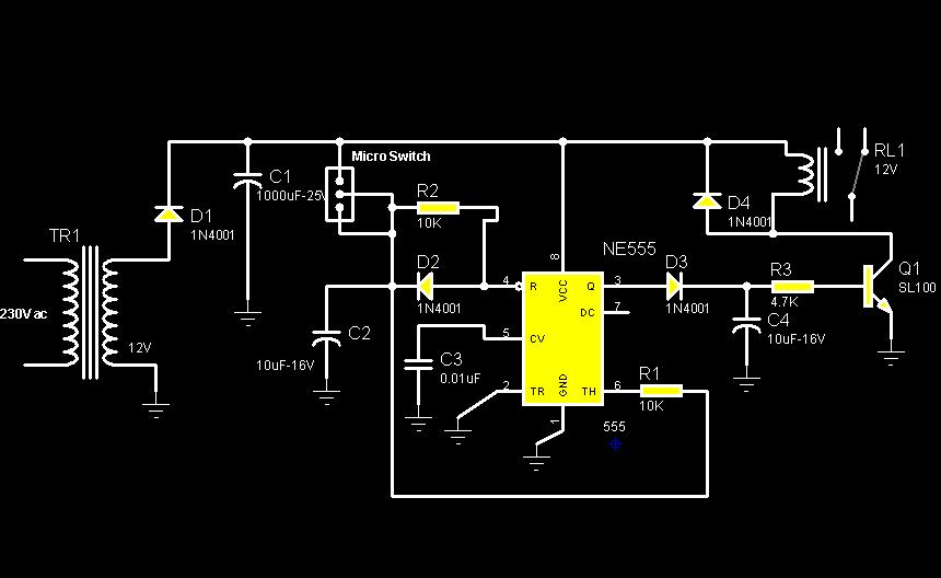
Rotation Sensor Circuit Using 555 PCB
The circuit diagram illustrates a rotation sensor that activates a device, such as a motor or buzzer, when the circuit assembly is rotated. The design is based on the fundamental operation of a 555 timer.
The rotation sensor circuit utilizes a...
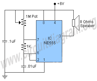
555 tone generator
This is a 555 tone generator circuit based on the NE555 timer IC. The NE555 is a well-known integrated circuit utilized in various applications and performs a multitude of functions. In this circuit, the IC operates as an astable oscillator,...
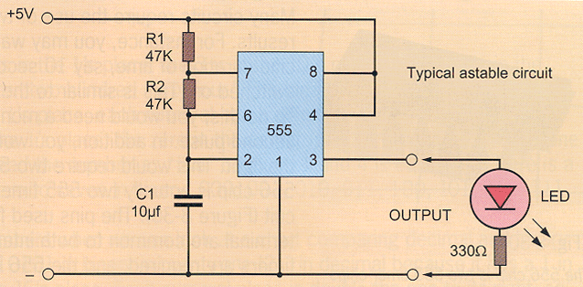
ksb3 timer
Understanding the three operational modes of the 555 timer reveals its numerous applications in integrated circuit designs. In oscillator mode, the 555 timer serves as a basic clock pulse generator, capable of frequencies up to 1 or 2 MHz. The...
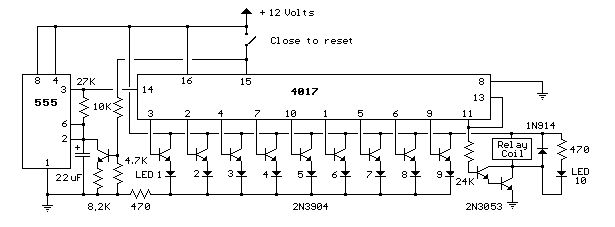
relay circuit 9 second led timer
This circuit provides a visual 9-second delay using 10 LEDs before closing a 12-volt relay. When the switch is closed, the 4017 decade counter will reset to zero, illuminating the LED connected to pin 3. The output at pin 3...
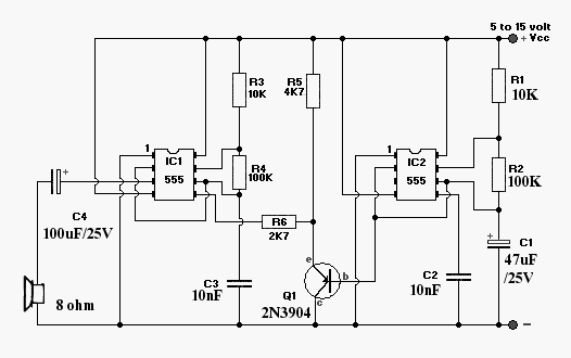
Wailing Alarm Siren
This alarm siren circuit produces a warbling sound, suitable for use in toys or security alarms. The circuit employs two 555 IC oscillators. The first oscillator generates the audio frequency, while the second oscillator creates a modulating signal. This modulating...
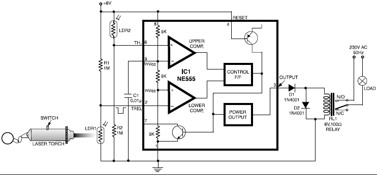
laser controlled on off switch
This circuit is designed around a 555 timer and utilizes a minimal number of components. Its simplicity allows even beginners to easily assemble and operate it as a control device. A readily available laser pointer can be used to activate...
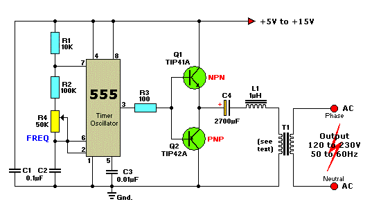
12VDC to 220VAC Inverter Circuit Using IC 555
This circuit is a simple 12V DC to 220V AC inverter that produces an AC output at line frequency, specifically 220V AC, or other voltages by selecting transformer T1. The 555 integrated circuit (IC) is configured as a low-frequency oscillator,...
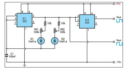
555 Timer Circuit With Variable On/Off Times
This circuit allows for the independent variation of the on/off times of a 555 timer across a wide range. This capability is not achievable with a conventional 555 timer circuit.
The described circuit enhances the functionality of the standard 555 timer...

new pedal schematic
U1 (555 in monostable mode) generates a square wave signal that corresponds to the input signal. This square wave is then sent to the mixer (U2) along with the original signal for mixing, effectively functioning as a frequency doubler. Each...