


65W PoE DC-DC converter
#PoE
#DC-DC converter
#switching regulator
#high-voltage
#NCP1031
#power supply
#Ethernet
#5V
#efficiency
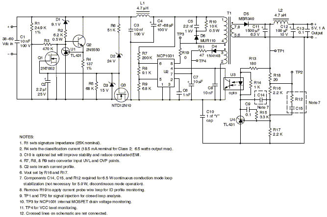
Description: This document presents a solution for one aspect of Power over Ethernet (PoE) using the ON Semiconductor NCP1031 series of monolithic, high-voltage switching regulators with internal MOSFETs. It details the construction of an affordable, high-efficiency 5.0 V DC power supply with an output power range of 5.0 to 6.5 W, which is dependent on the conversion mode. The input circuitry for responding to PoE detection and classification protocols is also included. ON Semiconductor offers a demonstration printed circuit board (PCB) with this circuitry upon request. According to IEEE Standard 802.3AF, it is now feasible to inject DC power through Ethernet data transmission lines to power Ethernet communication devices, provided the end power requirement is less than 13 W. The parametric details of DC power transmission and associated terminology are outlined in this IEEE document. PoE consists of two power entities: Power Sourcing Equipment (PSE) and Powered Devices (PDs). PSEs typically provide 48 Vdc nominal to LAN cables, while PDs are small DC/DC converters at the load end that convert 48 V to logic levels such as 5.0 Vdc or 3.3 Vdc to power communications equipment. PDs must operate with a maximum average input power of 12.95 W and tolerate input voltage ranges of 36 to 57 Vdc. A specific protocol is required for detecting the PD (Signature Mode) and classifying it (Classification Mode) according to its maximum power level. The current drawn from the PSE must fall between the Iclass minimum and maximum values for a given power classification. The required resistor value (R4) for classification in the circuit described in this application note is also noted.
Signature detection occurs when the upstream PSE equipment detects the PD by injecting two different voltages between 2.8 and 10 Vdc into the PD input terminals. If the detected impedance of the PD, measured by the V/I slope, is between 23.7 KΩ and 26.25 KΩ, the PD is considered present. If the impedance is below 15 KΩ or above 33 KΩ, the PD is deemed absent, and no further voltage will be applied. In Classification mode, the PSE sources a voltage between 14.5 and 20.5 Vdc to the PD to classify it according to its intended power level based on the current drawn by the PD. Furthermore, the PD must include circuitry to limit the inrush current from the PSE to 400 mA when the input voltage is applied and to prevent any quiescent currents or impedances caused by the DC/DC converter from affecting the signature and classification processes.
The schematic in Figure 1 illustrates the input signature and classification circuitry designed using several discrete and cost-effective ON Semiconductor components, including the TL431 programmable reference, a 2N7002 signal level MOSFET, a 2N5550 NPN transistor, an NTD12N10 MOSFET, several Zener diodes, resistors, and capacitors. For signature detection, a 24.9 KΩ resistor (R1) is connected directly across the input. During signature detection, the input voltage remains below 10 V, and the constant current source formed by U1, Q2, and R4 is inactive due to the 9.1 V Zener voltage that must be exceeded to bias this circuit. Additionally, MOSFET Q3, which serves as a series input switch in the return leg of the DC/DC converter, remains off until the input voltage surpasses approximately 27 V, which is the cumulative voltage of D2's Zener voltage and the gate threshold of Q3. As the voltage increases to the classification level, D1 begins to conduct.
This comprehensive setup enables efficient power management and classification of devices powered through Ethernet, ensuring compliance with PoE standards while maintaining operational integrity for connected devices.A solution to one aspect of Power over Ethernet (PoE) is presented here utilizing the ON Semiconductor NCP1031 series of monolithic, high-voltage switching regulators with internal MOSFET. The application note provides details for constructing an inexpensive, high efficiency, 5. 0 V DC power supply with a power output of 5. 0 to 6. 5 W, (output power is conversion mode dependent ” see DC/DC converter operation description below). The associated input circuitry for responding to PoE detection and classification protocol is also included. ON Semiconductor can provide a demonstration printed-circuit-board (PCB) with this circuitry upon request.
As a result of IEEE Standard 802. 3AF, it is now possible to inject DC power through Ethernet data transmission lines to power Ethernet communication devices as long as the end power requirement is less than 13 W. The parametric details of DC power transmission and the associated terminology is outlined in this IEEE document.
POE consists of two power entities: Power Sourcing Equipment (PSE) and Powered Devices (PDs). The PSEs typically provide 48 Vdc nominal to the LAN cables while the PDs are small DC/DC converters at the load end of the cables which transform the 48 V to logic levels such as 5. 0 Vdc or 3. 3 Vdc or both, to power the communications equipment. The PDs should be able to operate with a maximum average input power of 12. 95 W and tolerate an input voltage range of 36 to 57 Vdc. In addition, a certain "protocol" is required in which the PD is detected (Signature Mode) and then classified (Classification Mode) according to its maximum power level.
Note that from the 4th and 5th columns on the table, that the current drawn from the PSE falls between the Iclass minimum and maximum values for a given power classification. The last column is the value of the resistor (R4) required for classification in the circuit described by this application note.
Signature detection: The upstream PSE equipment detects the PD by injecting two different voltages between 2. 8 and 10 Vdc into the PD input terminals. If the detected impedance of the PD as measured by the V/I slope is above 23. 7 K ©, and below 26. 25 K ©, the PD is considered present. If the impedance is less than 15 K, or greater than 33 K, the PD is considered not present, and no further voltage will be applied.
Classification mode: To classify the PD according to its intended power level, the PSE will again source a voltage between 14. 5 and 20. 5 Vdc to the PD. The classification is determined by the current drawn by the PD upon application of this voltage, and is summarized in the following table: In addition to the signature and classification circuitry, the PD must also include circuitry to limit the inrush current from the PSE to 400 mA when the input voltage is applied, and to prevent any quiescent currents or impedances caused by the DC/DC converter to be ignored during the signature and classification processes.
Referring to the schematic of Figure 1, the input signature and classification circuitry is designed around a few discrete and inexpensive ON Semiconductor parts that include the TL431 programmable reference, a 2N7002 signal level MOSFET, a 2N5550 NPN transistor, an NTD12N10 MOSFET and several Zener diodes and a few resistors and capacitors. For signature detection, a 24. 9 K resistor (R1) is placed directly across the input. Note that during signature detection, the input voltage is below 10 V and the constant current source formed by U1, Q2 and R4 is off because of the 9.
1 V Zener that must be overcome to bias this circuit. Note also that MOSFET Q3, which functions as a series input switch in the return leg of the DC/DC converter, will be off until the input voltage exceeds approximately 27 V. This voltage is the sum of D2`s Zener voltage and the gate threshold of Q3. As the voltage is ramped up to the classification level, D1 conducts above appro
Signature detection occurs when the upstream PSE equipment detects the PD by injecting two different voltages between 2.8 and 10 Vdc into the PD input terminals. If the detected impedance of the PD, measured by the V/I slope, is between 23.7 KΩ and 26.25 KΩ, the PD is considered present. If the impedance is below 15 KΩ or above 33 KΩ, the PD is deemed absent, and no further voltage will be applied. In Classification mode, the PSE sources a voltage between 14.5 and 20.5 Vdc to the PD to classify it according to its intended power level based on the current drawn by the PD. Furthermore, the PD must include circuitry to limit the inrush current from the PSE to 400 mA when the input voltage is applied and to prevent any quiescent currents or impedances caused by the DC/DC converter from affecting the signature and classification processes.
The schematic in Figure 1 illustrates the input signature and classification circuitry designed using several discrete and cost-effective ON Semiconductor components, including the TL431 programmable reference, a 2N7002 signal level MOSFET, a 2N5550 NPN transistor, an NTD12N10 MOSFET, several Zener diodes, resistors, and capacitors. For signature detection, a 24.9 KΩ resistor (R1) is connected directly across the input. During signature detection, the input voltage remains below 10 V, and the constant current source formed by U1, Q2, and R4 is inactive due to the 9.1 V Zener voltage that must be exceeded to bias this circuit. Additionally, MOSFET Q3, which serves as a series input switch in the return leg of the DC/DC converter, remains off until the input voltage surpasses approximately 27 V, which is the cumulative voltage of D2's Zener voltage and the gate threshold of Q3. As the voltage increases to the classification level, D1 begins to conduct.
This comprehensive setup enables efficient power management and classification of devices powered through Ethernet, ensuring compliance with PoE standards while maintaining operational integrity for connected devices.A solution to one aspect of Power over Ethernet (PoE) is presented here utilizing the ON Semiconductor NCP1031 series of monolithic, high-voltage switching regulators with internal MOSFET. The application note provides details for constructing an inexpensive, high efficiency, 5. 0 V DC power supply with a power output of 5. 0 to 6. 5 W, (output power is conversion mode dependent ” see DC/DC converter operation description below). The associated input circuitry for responding to PoE detection and classification protocol is also included. ON Semiconductor can provide a demonstration printed-circuit-board (PCB) with this circuitry upon request.
As a result of IEEE Standard 802. 3AF, it is now possible to inject DC power through Ethernet data transmission lines to power Ethernet communication devices as long as the end power requirement is less than 13 W. The parametric details of DC power transmission and the associated terminology is outlined in this IEEE document.
POE consists of two power entities: Power Sourcing Equipment (PSE) and Powered Devices (PDs). The PSEs typically provide 48 Vdc nominal to the LAN cables while the PDs are small DC/DC converters at the load end of the cables which transform the 48 V to logic levels such as 5. 0 Vdc or 3. 3 Vdc or both, to power the communications equipment. The PDs should be able to operate with a maximum average input power of 12. 95 W and tolerate an input voltage range of 36 to 57 Vdc. In addition, a certain "protocol" is required in which the PD is detected (Signature Mode) and then classified (Classification Mode) according to its maximum power level.
Note that from the 4th and 5th columns on the table, that the current drawn from the PSE falls between the Iclass minimum and maximum values for a given power classification. The last column is the value of the resistor (R4) required for classification in the circuit described by this application note.
Signature detection: The upstream PSE equipment detects the PD by injecting two different voltages between 2. 8 and 10 Vdc into the PD input terminals. If the detected impedance of the PD as measured by the V/I slope is above 23. 7 K ©, and below 26. 25 K ©, the PD is considered present. If the impedance is less than 15 K, or greater than 33 K, the PD is considered not present, and no further voltage will be applied.
Classification mode: To classify the PD according to its intended power level, the PSE will again source a voltage between 14. 5 and 20. 5 Vdc to the PD. The classification is determined by the current drawn by the PD upon application of this voltage, and is summarized in the following table: In addition to the signature and classification circuitry, the PD must also include circuitry to limit the inrush current from the PSE to 400 mA when the input voltage is applied, and to prevent any quiescent currents or impedances caused by the DC/DC converter to be ignored during the signature and classification processes.
Referring to the schematic of Figure 1, the input signature and classification circuitry is designed around a few discrete and inexpensive ON Semiconductor parts that include the TL431 programmable reference, a 2N7002 signal level MOSFET, a 2N5550 NPN transistor, an NTD12N10 MOSFET and several Zener diodes and a few resistors and capacitors. For signature detection, a 24. 9 K resistor (R1) is placed directly across the input. Note that during signature detection, the input voltage is below 10 V and the constant current source formed by U1, Q2 and R4 is off because of the 9.
1 V Zener that must be overcome to bias this circuit. Note also that MOSFET Q3, which functions as a series input switch in the return leg of the DC/DC converter, will be off until the input voltage exceeds approximately 27 V. This voltage is the sum of D2`s Zener voltage and the gate threshold of Q3. As the voltage is ramped up to the classification level, D1 conducts above appro
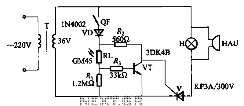
High-voltage isolation switch operation display circuit
High-voltage isolation switches must not be connected to loads that could create an arc, which may lead to a short circuit between the high-voltage bus and result in accidents that endanger both equipment and personnel safety. Consequently, high-voltage switchgear incorporates...
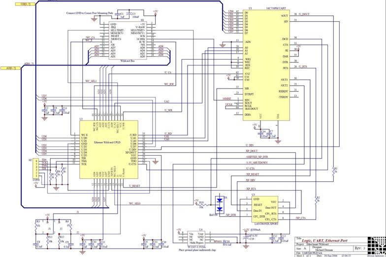
Ethernet Hardware Schematics
The EtherSmart Wildcard is based on the Lantronix Xport Ethernet device server, which is integrated into an RJ-45 connector housing. The Xport communicates data through a serial UART-USART interface, while the Wildcard bus operates as a parallel interface. A UART...
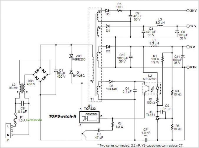
Designing Multiple Output Power Supplies With Topswitch
This application note describes a digital blood pressure meter concept that utilizes integrated pressure sensor analog signal-conditioning circuitry, microcontroller hardware/software, and a liquid crystal display. The sensing system measures cuff pressure (CP) and extracts pulses for analysis to determine systolic...
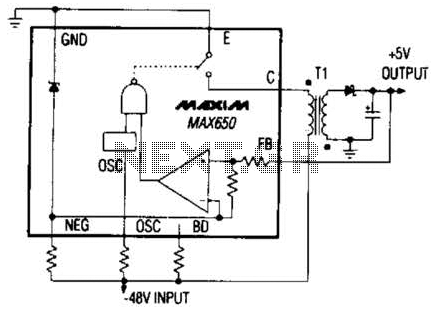
Switching Regulator Converter Circuit
The Max650 switching regulator generates a regulated 5 V output from large negative voltages, such as the -48 V commonly found on telephone lines. This power supply requires several external components, including a transformer, and is capable of delivering 250...
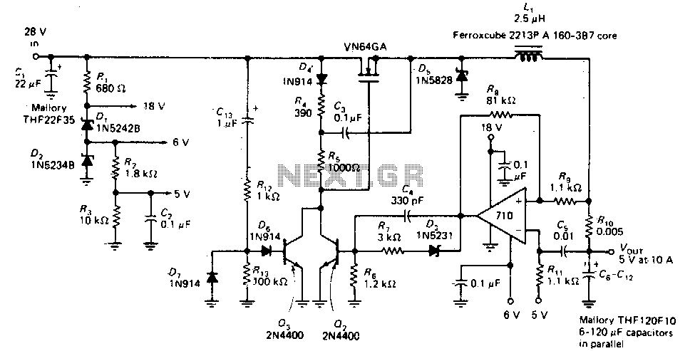
Switching regulator operating at 200Khz
This circuit provides a regulated DC output with less than 100 mV of ripple for microprocessor applications. The required operating voltages are derived from a bleeder resistor network connected across the unregulated 28 V supply. The output of the LM710...
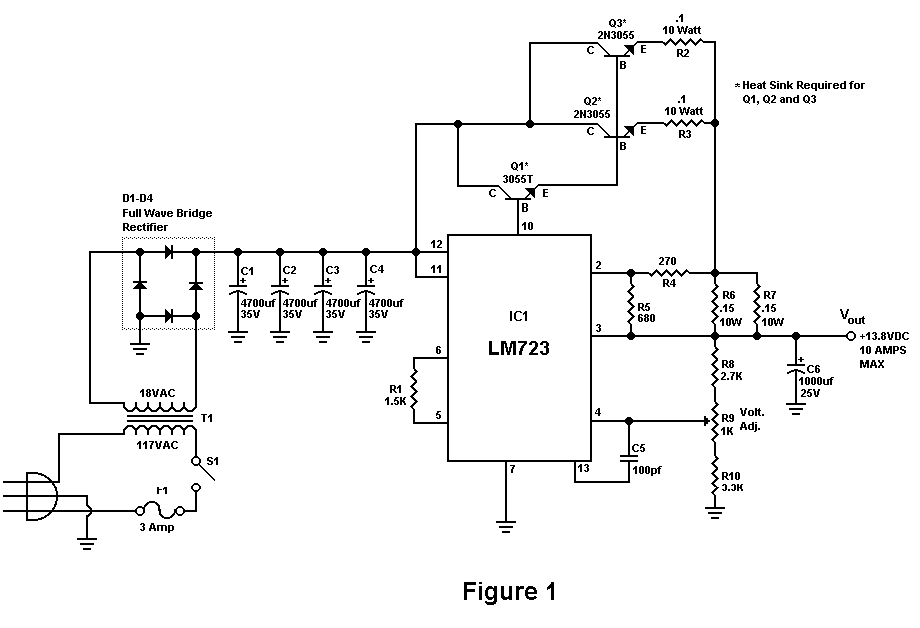
Build A 10 Amp 13.8 Volt Power Supply
Sometimes amateurs like to home-brew their power supplies instead of purchasing one off the shelf at any of the major ham radio retail dealers. The advantage to rolling your own power supply is that it teaches us how they work...
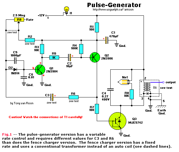
High-Voltage Pulse Generator
If you have ever wanted a high-voltage generator to create impressive lightning effects, conduct Kirlian photography experiments, or experiment with neon lights, this project is ideal. It describes a laboratory pulse generator utilizing an auto-ignition coil, capable of delivering a...

How to Boost Efficiency at Low Loads
Small additional circuitry during standby can significantly enhance efficiency. In a modern vehicle, multiple microcontrollers are required to support safety, navigation, entertainment, and comfort electronics.
The integration of additional circuitry during standby mode in automotive applications is crucial for optimizing power...
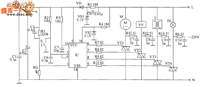
Industrial fuel oil furnace controller circuit diagram 2
The industrial fuel oil furnace controller circuit consists of a power supply circuit, a testing and ignition control circuit, and a control implementation circuit, as illustrated in the accompanying diagram. The power supply circuit includes a step-down capacitor (C6), a...