


A typical liquid crystal display inverter circuit OZ965
#LCD
#OZ965
#inverter circuit
#power supply
#backlight
#voltage regulation
#display
#electronics
#circuit design
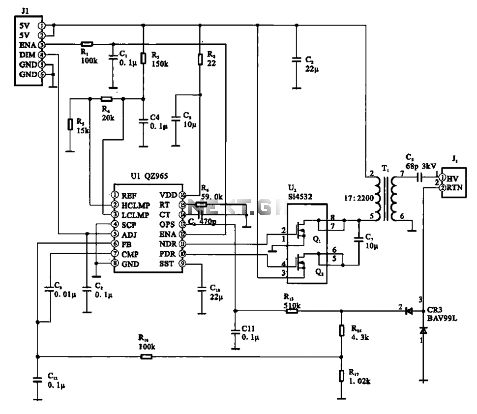
Description: A typical liquid crystal display inverter circuit (OZ965) is primarily controlled by the OZ965 chip. It includes a driving field effect transistor (U2), a step-up transformer, the backlight socket, and associated circuitry. A 5V DC voltage is provided by the control chip at pin J1. This voltage is filtered by capacitor C2, which drives a field effect transistor (U1) connected to the step-up transformer for power supply. An enable control signal (ENA) is input through pin J1 into the control chip. Once the inverter circuit is activated, the output from pin U1 generates two opposite phase PWM pulse signals, which drive the field effect transistor (U1) and increase the voltage from the step-up transformer to approximately 800V, powering the backlight lamp through the backlight socket.
The liquid crystal display inverter circuit utilizing the OZ965 chip is designed to efficiently convert low voltage DC into high voltage AC, suitable for powering the backlight of LCD panels. The circuit begins with a 5V DC input supplied to the OZ965 control chip via pin J1, which is responsible for regulating the operation of the entire circuit.
Capacitor C2 plays a crucial role in filtering the input voltage to ensure a stable supply to the field effect transistor (U1). This transistor acts as a switch that modulates the current flowing into the step-up transformer. The transformer is essential for elevating the voltage from the low 5V level to the required high voltage, which is necessary for the operation of the backlight lamps.
The enable control signal (ENA) is sent to the OZ965 chip, indicating that the inverter circuit should begin operation. Upon activation, the chip generates two PWM signals at the output pin U1, which are 180 degrees out of phase. These signals drive the field effect transistor (U1) in a manner that allows for efficient energy transfer to the step-up transformer.
As a result of this operation, the transformer steps up the voltage significantly, reaching approximately 800V. This high voltage is then delivered to the backlight lamp socket, effectively illuminating the LCD panel. The design of this inverter circuit exemplifies a compact and efficient solution for powering LCD backlights, utilizing a combination of modern semiconductor technology and traditional transformer principles. The overall configuration ensures reliable performance and longevity of the backlight system in various display applications.A typical liquid crystal display inverter circuit (OZ965) It shows a typical liquid crystal display of the inverter circuit, which is mainly controlled by the 02965 chip, the d riving field effect transistor U2, step-up transformer, the backlight socket part and associated circuitry configured. After 5v DC voltage by the control chip UI widget Jl provided (02 965) of the pin DC voltage; at the same time, by filtering electrical pit C2 after driving to a field effect transistor Ul step-up transformer and power supply; enable control signal (ENA) through plug Jl feet into the control chip, after the inverter circuit starts from the Ul feet pin output two opposite phase PWM pulse signal, the drive field effect transistor Ul put into large after the step-up transformer, the rise the pulse voltage transformer voltage up to about 800V, by backlight backlight lamp socket to power.
The liquid crystal display inverter circuit utilizing the OZ965 chip is designed to efficiently convert low voltage DC into high voltage AC, suitable for powering the backlight of LCD panels. The circuit begins with a 5V DC input supplied to the OZ965 control chip via pin J1, which is responsible for regulating the operation of the entire circuit.
Capacitor C2 plays a crucial role in filtering the input voltage to ensure a stable supply to the field effect transistor (U1). This transistor acts as a switch that modulates the current flowing into the step-up transformer. The transformer is essential for elevating the voltage from the low 5V level to the required high voltage, which is necessary for the operation of the backlight lamps.
The enable control signal (ENA) is sent to the OZ965 chip, indicating that the inverter circuit should begin operation. Upon activation, the chip generates two PWM signals at the output pin U1, which are 180 degrees out of phase. These signals drive the field effect transistor (U1) in a manner that allows for efficient energy transfer to the step-up transformer.
As a result of this operation, the transformer steps up the voltage significantly, reaching approximately 800V. This high voltage is then delivered to the backlight lamp socket, effectively illuminating the LCD panel. The design of this inverter circuit exemplifies a compact and efficient solution for powering LCD backlights, utilizing a combination of modern semiconductor technology and traditional transformer principles. The overall configuration ensures reliable performance and longevity of the backlight system in various display applications.A typical liquid crystal display inverter circuit (OZ965) It shows a typical liquid crystal display of the inverter circuit, which is mainly controlled by the 02965 chip, the d riving field effect transistor U2, step-up transformer, the backlight socket part and associated circuitry configured. After 5v DC voltage by the control chip UI widget Jl provided (02 965) of the pin DC voltage; at the same time, by filtering electrical pit C2 after driving to a field effect transistor Ul step-up transformer and power supply; enable control signal (ENA) through plug Jl feet into the control chip, after the inverter circuit starts from the Ul feet pin output two opposite phase PWM pulse signal, the drive field effect transistor Ul put into large after the step-up transformer, the rise the pulse voltage transformer voltage up to about 800V, by backlight backlight lamp socket to power.
markII
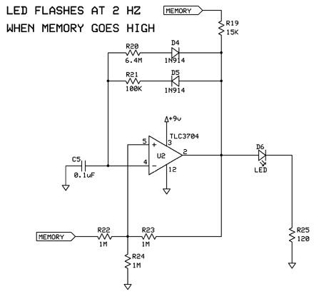
The following circuits are presented in a logical order from initial power-up to the additional features incorporated at the end of the project. A less organized version of the Mark II design exists, but this is the sanitized and organized...
power supply alarm circuit
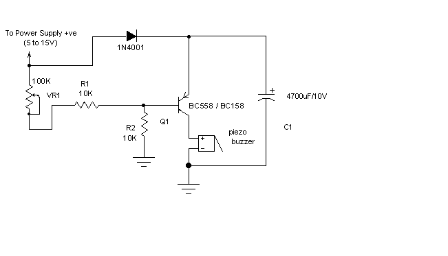
Most of the power supply failure indicator circuits need a separate power supply for themselves. But the alarm circuit presented here needs no additional supply source. It employs an electrolytic capacitor to store adequate charge, to feed power to the...
Structural analysis of switching power supply
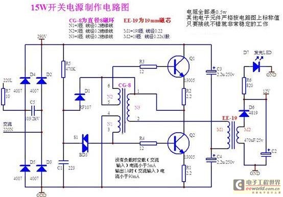
A daily switching power supply primarily provides direct current (DC) power to electronic devices. The required DC voltage for electronic devices typically ranges from several volts to over ten volts, while the input voltage from the mains supply is either...
how lcd display interface circuit works 20
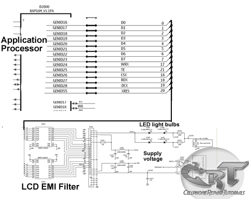
An LCD (liquid crystal display) is an electronically modulated optical device composed of multiple pixels filled with liquid crystals, arranged in front of a light source (backlight) or reflector to generate images in either color or monochrome. The block diagram...
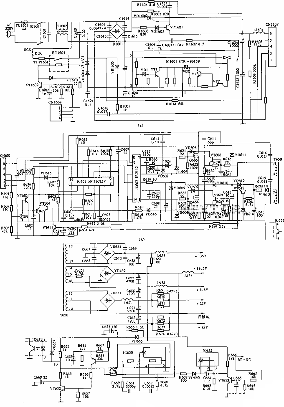
Sony KV-S29MHl TV switching power supply (SIR a 80145A) circuit diagram
The circuit of the Sony KV-S29MHl (S Movement series) TV switching power supply (SIR a 80145A) consists of three main sections: (A) the power oscillation part, (B) the regulator part, and (C) the output section.
The Sony KV-S29MHl TV switching power...
PM4040F application circuit switching power supply drive
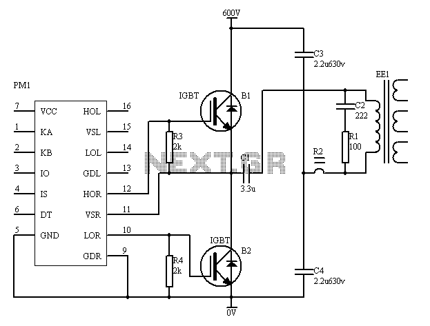
The PM4040F is utilized in switching power supply applications for medium power ranges. It is designed to drive power supplies between 200W and 800W, as illustrated in the accompanying bridge circuit. For power applications below 1000W, an alternative circuit configuration...
A 12 Volt Switching Power Supply
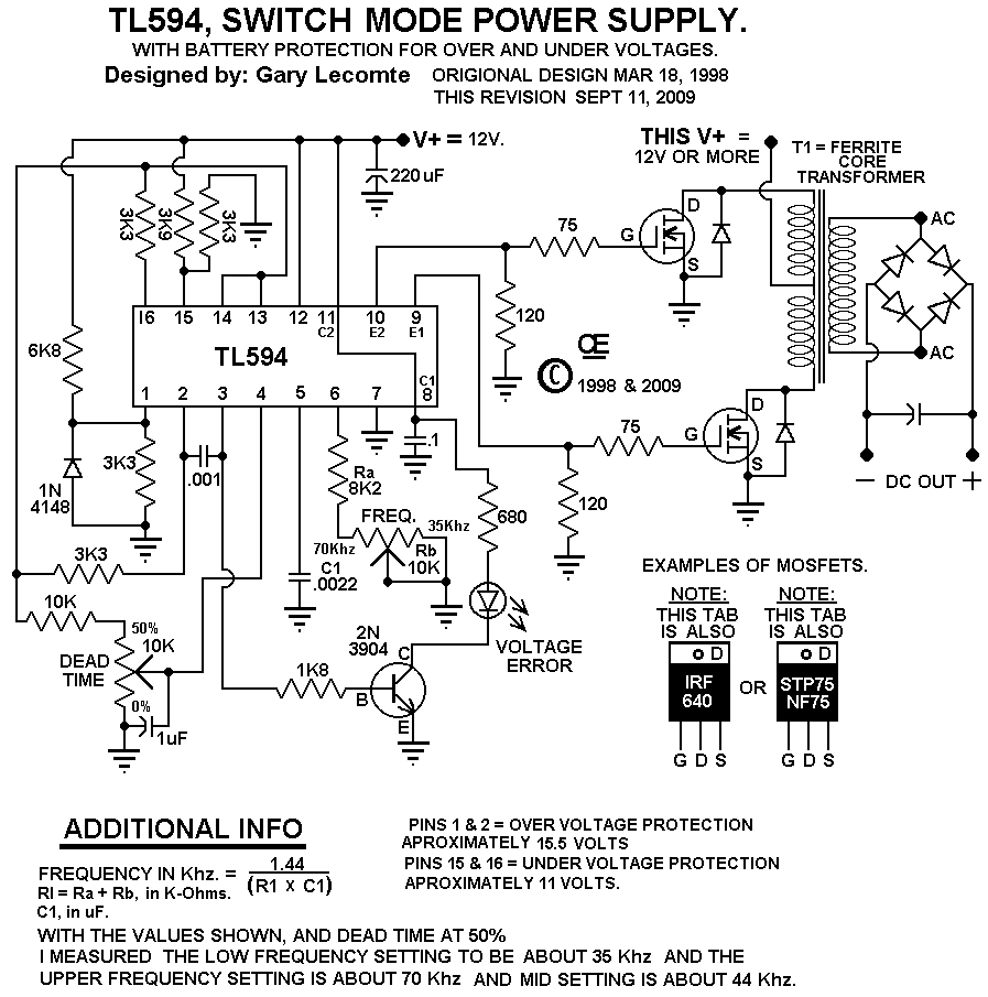
This circuit is designed for individuals needing to boost or drop a voltage. The output operates at high frequency but can be rectified and filtered to provide a DC output. When rectifying high frequencies, it is essential to utilize high-speed...
KC2ZPLs Web Design and Electronic Home
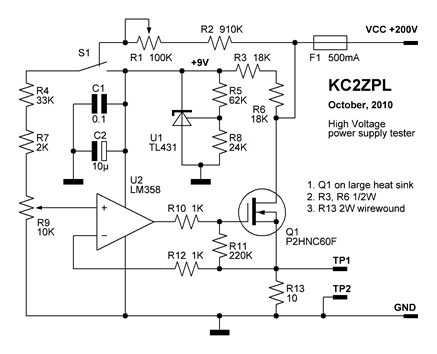
Now that these power supplies are available, it would be beneficial to evaluate their performance. Traditionally, an adjustable load (a robust resistor) is connected to the output to measure both output voltage and current at various points. This allows for...

capacitor Explaining a car voltage regulator circuit
The circuit regulates approximately 12V from the car battery down to 5V for use by an Atmel AVR microcontroller. The presence of two capacitors on each side of the linear regulator LM7805 raises questions regarding their purpose. It is suggested...