


ADP1821 Step Down DC-to-DC Converter
#ADP1821
#DC-to-DC converter
#step-down
#PWM
#voltage regulation
#synchronous controller
#power management
#switching regulator
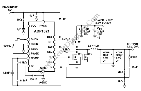
Description: This is an ADP1821 step-down DC-to-DC converter circuit. This circuit utilizes the ADP1821, which is a synchronous pulse-width-modulated (PWM) step-down controller.
The ADP1821 is designed to efficiently convert a higher input voltage to a lower output voltage while maintaining high performance and efficiency. This device operates in a synchronous mode, allowing for reduced power loss and improved efficiency compared to non-synchronous designs. The PWM control scheme enables precise regulation of the output voltage, making the circuit suitable for various applications, including powering microcontrollers, sensors, and other electronic devices.
The circuit typically includes several key components: the ADP1821 IC itself, input and output capacitors, an inductor, and a diode. The input capacitors serve to stabilize the input voltage and reduce voltage ripple, while the output capacitors help maintain a steady output voltage with minimal ripple. The inductor is critical for energy storage and transfer; it smooths the current flowing to the load, helping to maintain a consistent output voltage.
In operation, the ADP1821 modulates the duty cycle of the switching signal to control the amount of energy delivered to the output. The feedback loop monitors the output voltage and adjusts the PWM signal accordingly, ensuring that the output remains stable despite variations in load current or input voltage. This feedback mechanism is essential for maintaining the desired output voltage under different operating conditions.
The design of the circuit should also consider thermal management, as the ADP1821 can generate heat during operation. Adequate heat sinking or thermal vias may be required to ensure reliable performance. Additionally, careful selection of the inductor and capacitors is important to optimize the transient response and minimize output voltage ripple.
Overall, the ADP1821 step-down DC-to-DC converter circuit is a robust solution for efficiently powering electronic devices from higher voltage sources, making it a valuable component in modern electronic design.This is a ADP1821 Step Down DC-to-DC Converter circuit. This circuit uses ADP1821 that is synchronous pulse-width-modulated (PWM), step-down controller,.
The ADP1821 is designed to efficiently convert a higher input voltage to a lower output voltage while maintaining high performance and efficiency. This device operates in a synchronous mode, allowing for reduced power loss and improved efficiency compared to non-synchronous designs. The PWM control scheme enables precise regulation of the output voltage, making the circuit suitable for various applications, including powering microcontrollers, sensors, and other electronic devices.
The circuit typically includes several key components: the ADP1821 IC itself, input and output capacitors, an inductor, and a diode. The input capacitors serve to stabilize the input voltage and reduce voltage ripple, while the output capacitors help maintain a steady output voltage with minimal ripple. The inductor is critical for energy storage and transfer; it smooths the current flowing to the load, helping to maintain a consistent output voltage.
In operation, the ADP1821 modulates the duty cycle of the switching signal to control the amount of energy delivered to the output. The feedback loop monitors the output voltage and adjusts the PWM signal accordingly, ensuring that the output remains stable despite variations in load current or input voltage. This feedback mechanism is essential for maintaining the desired output voltage under different operating conditions.
The design of the circuit should also consider thermal management, as the ADP1821 can generate heat during operation. Adequate heat sinking or thermal vias may be required to ensure reliable performance. Additionally, careful selection of the inductor and capacitors is important to optimize the transient response and minimize output voltage ripple.
Overall, the ADP1821 step-down DC-to-DC converter circuit is a robust solution for efficiently powering electronic devices from higher voltage sources, making it a valuable component in modern electronic design.This is a ADP1821 Step Down DC-to-DC Converter circuit. This circuit uses ADP1821 that is synchronous pulse-width-modulated (PWM), step-down controller,.
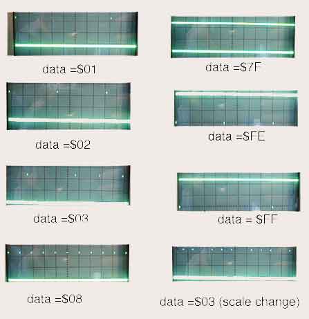
8 Channel PWM with AT90S1200
The assembly code given here was written to see what it would take to make an AT90S1200 generate 8 channels of proper PWM. In this case, by proper, I mean with the maximum high frequency content consistent with the needed...
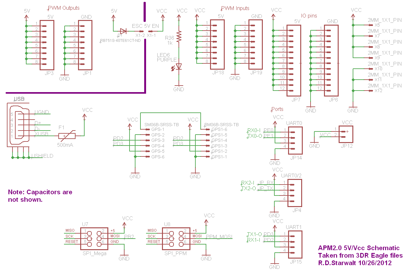
APM2.0 5V/Vcc Schematic
The PWM Output section has been separated into the upper left corner, delineated by a heavy purple line that is bridged by jumper JP1 on the APM2.0. This design choice highlights that diode D1 allows current to pass through JP1,...
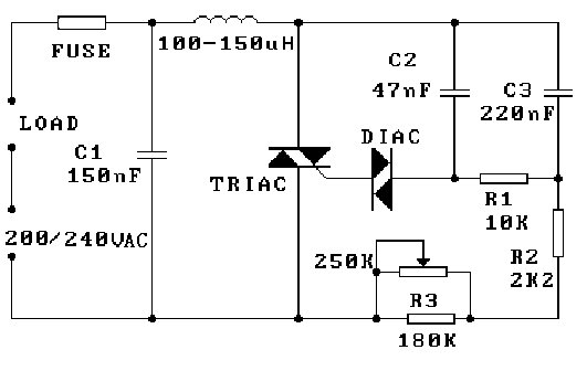
PWM to vary the light intensity of a 220V bulb
A 220V bulb is connected such that one end of the relay is linked to a 220V DC source and the other end is connected to ground. The switching between these two points is controlled by a PWM output as...
Voltage regulator for projection lamp
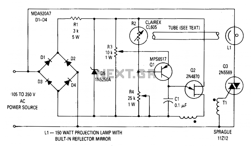
The circuit regulates the RMS output voltage across a load, specifically a projection lamp, to 100 volts ±2% for input voltages ranging from 105 to 250 volts AC. This regulation is achieved by indirectly sensing the light output of lamp...
Variable charger circuit Schematic Diagram
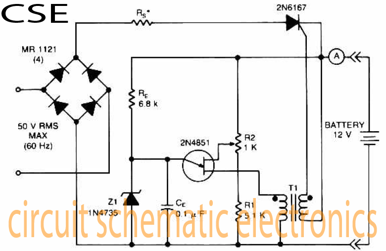
The accumulator charger circuit must provide a voltage that matches the specifications of the batteries being charged. For a 12-volt accumulator, the output voltage should not exceed 12 volts, nor should it fall significantly below this threshold. Failure to maintain...
pwm 01
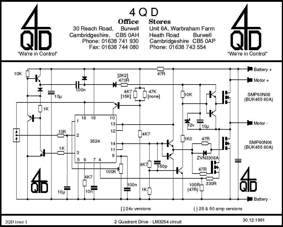
A commercial motor controller is more than just a circuit designed to adjust the speed of a motor. It encompasses various features that enhance its functionality, which are explained in a guided overview. To effectively control the speed of a...
PWM Controller Circuit
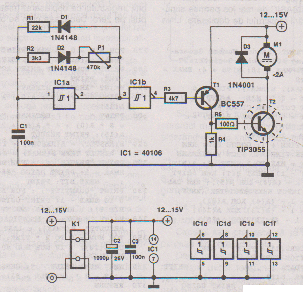
This PWM controller circuit is suitable for managing small motors with a maximum current consumption of 2A. For higher currents, additional cooling is required.
The PWM (Pulse Width Modulation) controller circuit is designed to efficiently control the speed of small DC...
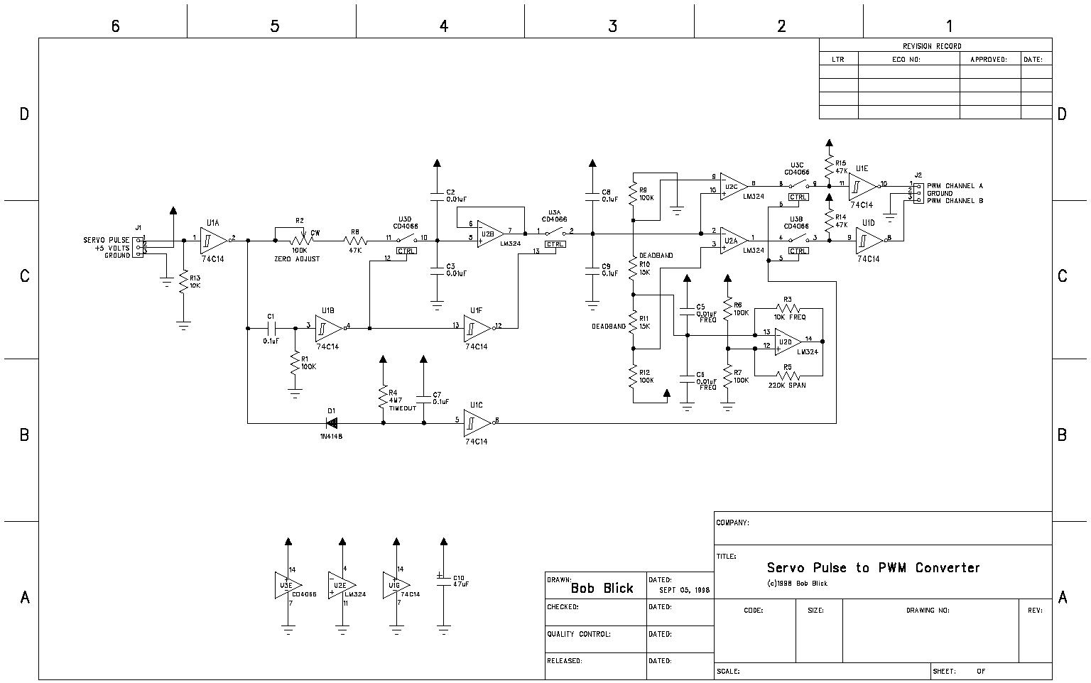
Servo pulse to PWM converter
The circuit presented on this page attempts to be an interface to convert pulses such as provided by a Basic Stamp or R/C receiver to a dual PWM (Pulse Width Modulation) signal required by an H-bridge. The simplest circuit would...
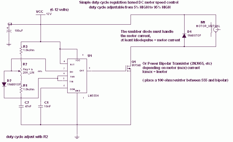
DC motor PWM speed control
The 555 IC is wired as an astable and the frequency is constant and independent of the duty cycle, as the total resistance (R charge + R discharge, notice the diode) is constant and equal to 22Kohm (giving a frequency...