


Automated instrumentation wiring using interference filters
#automated wiring
#interference filters
#harmonic processing
#field strength
#instrumentation
#inverter
#radiation
#electrical noise
#signal processing
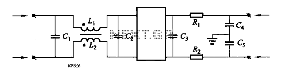
Description: Automated instrumentation wiring using interference filters for the inverter is not as effective for harmonic processing. When operational, it will radiate a strong field strength due to high amplitude electromagnetic waves. If the meter is installed in the automation system with a distance of less than 200mm and is not placed on the same layer as the shielding box, additional errors may occur. It is crucial to properly connect the instrument ground terminal. Furthermore, the instrument's input cable and power cord should undergo a filtering process. The capacitor should be selected as 0.1μF, 250V; the inductance should be 10mH with a DC resistance of less than 5Ω; and the resistor should be 100Ω, 1/2W.
Automated instrumentation wiring employing interference filters is essential for minimizing the effects of electromagnetic interference (EMI) on inverter systems. Inverters, which convert direct current (DC) to alternating current (AC), can generate significant electromagnetic emissions, especially when operating under high load conditions. These emissions can distort the readings of sensitive instrumentation and lead to inaccuracies in measurements.
To mitigate these issues, proper installation practices must be followed. It is recommended that the distance from the meter to the inverter should not exceed 200mm, and the meter should not be positioned on the same layer as the shielding box. This configuration helps reduce the coupling of electromagnetic fields into the measurement circuit, thereby minimizing potential errors.
Grounding is another critical aspect of the installation. The instrument ground terminal must be securely connected to ensure a stable reference point for the measurements and to prevent ground loops, which can introduce additional noise into the system.
The filtering process for the instrument's input cable and power cord is vital for suppressing high-frequency noise. The selected capacitor (0.1μF, 250V) serves to block high-frequency noise while allowing the desired signals to pass through. The inductance of 10mH, with a DC resistance of less than 5Ω, aids in further filtering out unwanted electromagnetic interference. The resistor (100Ω, 1/2W) is included in the design to provide a damping effect, which can help stabilize the circuit and improve the overall response time of the instrumentation.
In summary, careful consideration of the installation parameters, grounding practices, and component selection is essential for ensuring accurate and reliable operation of automated instrumentation in the presence of high amplitude electromagnetic waves. Proper implementation of these measures will enhance the performance of the system and reduce measurement errors significantly. Automated instrumentation wiring using interference filters for the inverter is not as harmonic processing and the like, when the work will be radiated field strength of strong , high amplitude electromagnetic wave, if the meter is installed in the automation from its lack of 200mm, placed in not the same layer as the shielding box, the meter may yield additional error birth. This time should be the instrument ground terminal properly connected, then the instrument input cable and power cord for the filtering process, as shown in FIG.
Now the capacitor C selection 0. lFtF, 250V; inductance L take lOmH, DC resistance of less than 5Q; resistor R to select 100n, 1/2W.
Automated instrumentation wiring employing interference filters is essential for minimizing the effects of electromagnetic interference (EMI) on inverter systems. Inverters, which convert direct current (DC) to alternating current (AC), can generate significant electromagnetic emissions, especially when operating under high load conditions. These emissions can distort the readings of sensitive instrumentation and lead to inaccuracies in measurements.
To mitigate these issues, proper installation practices must be followed. It is recommended that the distance from the meter to the inverter should not exceed 200mm, and the meter should not be positioned on the same layer as the shielding box. This configuration helps reduce the coupling of electromagnetic fields into the measurement circuit, thereby minimizing potential errors.
Grounding is another critical aspect of the installation. The instrument ground terminal must be securely connected to ensure a stable reference point for the measurements and to prevent ground loops, which can introduce additional noise into the system.
The filtering process for the instrument's input cable and power cord is vital for suppressing high-frequency noise. The selected capacitor (0.1μF, 250V) serves to block high-frequency noise while allowing the desired signals to pass through. The inductance of 10mH, with a DC resistance of less than 5Ω, aids in further filtering out unwanted electromagnetic interference. The resistor (100Ω, 1/2W) is included in the design to provide a damping effect, which can help stabilize the circuit and improve the overall response time of the instrumentation.
In summary, careful consideration of the installation parameters, grounding practices, and component selection is essential for ensuring accurate and reliable operation of automated instrumentation in the presence of high amplitude electromagnetic waves. Proper implementation of these measures will enhance the performance of the system and reduce measurement errors significantly. Automated instrumentation wiring using interference filters for the inverter is not as harmonic processing and the like, when the work will be radiated field strength of strong , high amplitude electromagnetic wave, if the meter is installed in the automation from its lack of 200mm, placed in not the same layer as the shielding box, the meter may yield additional error birth. This time should be the instrument ground terminal properly connected, then the instrument input cable and power cord for the filtering process, as shown in FIG.
Now the capacitor C selection 0. lFtF, 250V; inductance L take lOmH, DC resistance of less than 5Q; resistor R to select 100n, 1/2W.
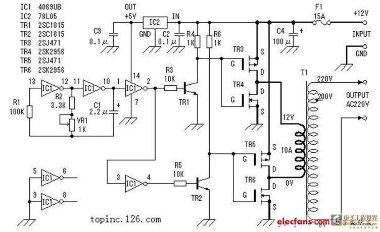
Circuit DIY of the inverter (picture and text is explained in detail)
The inverter described in this text utilizes a MOS field-effect transistor and a standard power transformer. Its output power is determined by the capabilities of both the MOS field-effect transistor and the transformer, eliminating the need for complex voltage transformer...
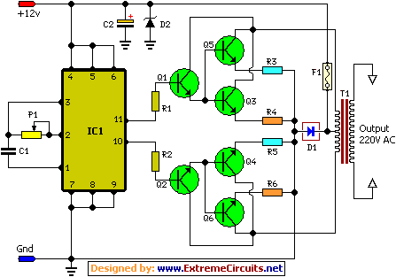
100W Inverter Circuit
This is a 100 Watt inverter circuit designed with a minimal number of components. The circuit utilizes the CD4047 integrated circuit from Texas Instruments to generate 100 Hz pulses, and it employs four 2N3055 transistors to drive the load. The...
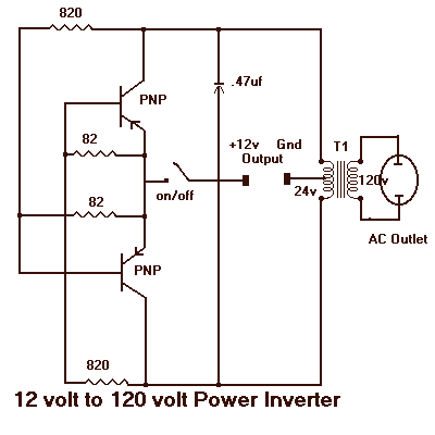
12 to 120 Volt Inverter
It will supply 15 watts of AC power to a device. It should power lamps, shavers, small stereos and small appliances. If you draw too much power the circuit will shut down all by itself. The output of this circuit...
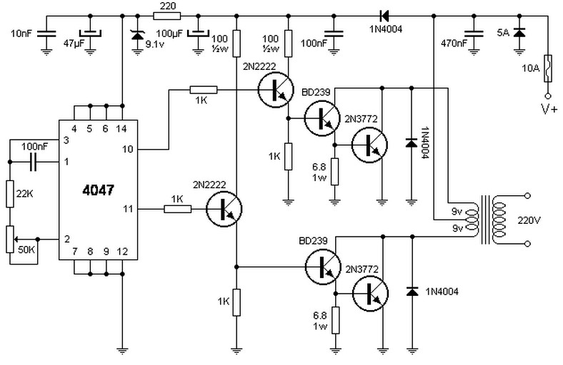
100W inverter 12V to 220VAC
To lower or raise a specific voltage, a transformer is typically used; however, this component does not operate with direct current, which is available in batteries or vehicles. Therefore, an oscillator is required to generate alternating current. The integrated circuit...
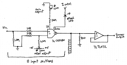
Interpolating Scanner Circuit
This design is for an interpolating scanner, a circuit featuring multiple signal inputs, a control voltage input, and a signal output. The output selectively transitions between inputs, smoothly fading from one to the next as the control voltage increases. A...
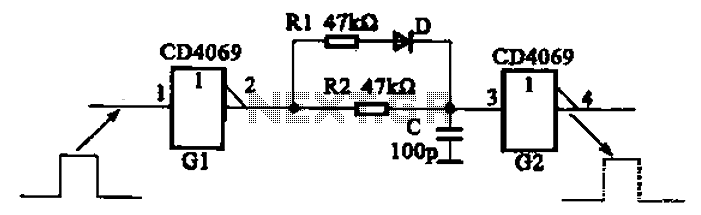
And broadening the delay circuit
The inverter circuit using CD4069 is configured with a delay and width adjustment. When the output of the inverter (G1) is high, the capacitor (C) charges through resistor (R1) and diode (D). The voltage across capacitor C quickly reaches the...
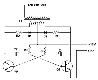
12 Vdc - 120 Vac Inverter
An Inverter is a device that converts 12 volts d.c to 120 volts a.c., which is what we use in our homes. This project will handle about 300 watts, which is perfect for lights, small T.V.s and radio equipment. This...
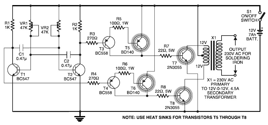
Inverter circuit for soldering iron
Simple Inverter for Soldering Iron. This is a straightforward and cost-effective inverter designed to operate small power soldering irons (25W, 35W, etc.) in the absence of mains supply. The circuit requires eight transistors along with several resistors and capacitors. It...
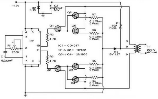
100W Inverter
The schematic diagram of a 100W inverter circuit converts a 12V DC input to a 220V AC output. The circuit is built using the CD4047 integrated circuit, which generates a sine wave signal at 50Hz. The power transistor 2N3055 amplifies...