


Boost ConverterCircuit Based On The 555 IC
#555 IC
#boost converter
#voltage step-up
#DC-DC converter
#power electronics
#switching regulator
#circuit diagram
#off the shelf components
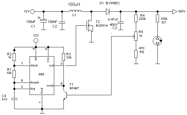
Description: The following circuit illustrates a Boost Converter Circuit Diagram. This circuit is based on the 555 IC. Features: it only requires off-the-shelf components.
The Boost Converter is a type of DC-DC converter that steps up the input voltage to a higher output voltage while maintaining the same power level, subject to efficiency constraints. The circuit utilizes the 555 timer IC, which is a versatile and widely used integrated circuit in various applications, including timing, pulse generation, and oscillator functions.
In this specific configuration, the 555 timer is set up in astable mode, generating a square wave output. This pulse signal is used to control a switching device, typically a transistor, which connects and disconnects the input voltage to an inductor. As the transistor switches on and off, energy is stored in the inductor during the 'on' phase and released to the output during the 'off' phase, effectively increasing the voltage.
The essential components of the circuit include:
1. **555 Timer IC**: Configured to produce a pulse-width modulated (PWM) signal that controls the transistor.
2. **Inductor**: This component stores energy when the transistor is on and releases it to the output when the transistor is off.
3. **Diode**: A flyback diode is used to prevent back EMF from the inductor from damaging the transistor.
4. **Capacitor**: This component smooths out the output voltage, reducing ripple and ensuring a stable voltage supply.
5. **Resistors**: These are used to set the timing characteristics of the 555 timer and to limit the current through the circuit.
The circuit's design allows for flexibility in output voltage by adjusting the duty cycle of the PWM signal generated by the 555 timer. By varying the resistor and capacitor values in the timing circuit, the frequency and duration of the pulse can be modified, thus changing the output voltage level.
Overall, this Boost Converter Circuit based on the 555 IC is an efficient and cost-effective solution for applications requiring a higher voltage from a lower voltage source, utilizing readily available components.The following circuit shows about Boost Converter Circuit Diagram. This Circuit Based On The 555 IC. Featrures: only requires an `of the shelf` ..
The Boost Converter is a type of DC-DC converter that steps up the input voltage to a higher output voltage while maintaining the same power level, subject to efficiency constraints. The circuit utilizes the 555 timer IC, which is a versatile and widely used integrated circuit in various applications, including timing, pulse generation, and oscillator functions.
In this specific configuration, the 555 timer is set up in astable mode, generating a square wave output. This pulse signal is used to control a switching device, typically a transistor, which connects and disconnects the input voltage to an inductor. As the transistor switches on and off, energy is stored in the inductor during the 'on' phase and released to the output during the 'off' phase, effectively increasing the voltage.
The essential components of the circuit include:
1. **555 Timer IC**: Configured to produce a pulse-width modulated (PWM) signal that controls the transistor.
2. **Inductor**: This component stores energy when the transistor is on and releases it to the output when the transistor is off.
3. **Diode**: A flyback diode is used to prevent back EMF from the inductor from damaging the transistor.
4. **Capacitor**: This component smooths out the output voltage, reducing ripple and ensuring a stable voltage supply.
5. **Resistors**: These are used to set the timing characteristics of the 555 timer and to limit the current through the circuit.
The circuit's design allows for flexibility in output voltage by adjusting the duty cycle of the PWM signal generated by the 555 timer. By varying the resistor and capacitor values in the timing circuit, the frequency and duration of the pulse can be modified, thus changing the output voltage level.
Overall, this Boost Converter Circuit based on the 555 IC is an efficient and cost-effective solution for applications requiring a higher voltage from a lower voltage source, utilizing readily available components.The following circuit shows about Boost Converter Circuit Diagram. This Circuit Based On The 555 IC. Featrures: only requires an `of the shelf` ..
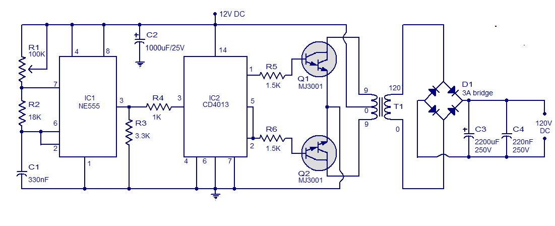
Simple Circuit 12V to 120V DC DC Converter
This is a simple circuit designed to convert 12V DC to 120V DC. The circuit comprises two main phases: the inverter stage and the rectifier and filter stage. The NE555 integrated circuit (IC1) is configured as an astable multivibrator, operating...
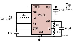
Micropower 1A Boost Converter with Schottky and Output Disconnect
The LT3473 and LT3473A are micropower step-up DC/DC converters that integrate a Schottky diode and output disconnect circuitry within low-profile DFN packages. Their compact size, high integration level, and utilization of small surface-mount technology (SMT) components result in a solution...
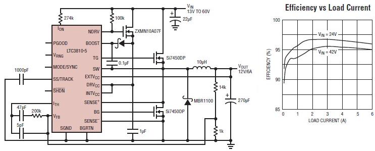
12 volt switching power supply using LTC3810-5 switching regulator
The LTC3810-5 synchronous step-down switching regulator controller allows for the design of a straightforward 12-volt switching power supply electronic project with minimal external components. This controller can directly reduce voltages from up to 60V, making it suitable for telecommunications and...
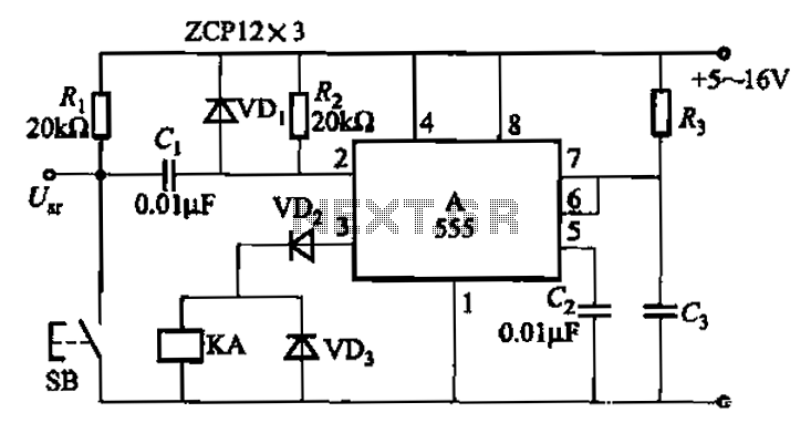
555 IC using a delay circuit 2
The 555 integrated circuit is utilized in a delay circuit configuration, functioning as a one-shot timer. The delay time can be adjusted using resistor R3 and capacitor C3. Typical values for R3 range from 1 kΩ to 10 MΩ, while...
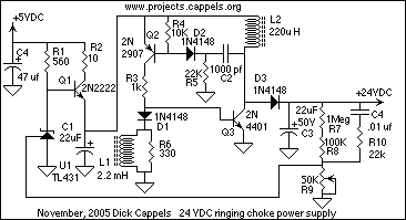
DC to DC Converter
The intended use of the 24 volts is to power an amplifier that will supply wave forms of up to a couple hundred Hz to bias a varactor or pair of varactors in an RF circuit. This meant that the...
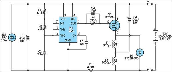
555 IC For 12V Lead Acid Battery Desulphator Circuit
The following circuit illustrates a 6/12/24V Lead Acid Battery Charger Circuit Diagram. Features: It is essentially a high-voltage pulse generator.
The circuit diagram for a 6/12/24V Lead Acid Battery Charger is designed to efficiently charge lead-acid batteries of varying voltages. The...
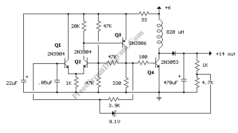
Transformerless Voltage Booster Circuit: A DC-DC Step-Up Switching Regulator Using Transistors
A DC-to-DC step-up converter is typically implemented using a transformer, which converts DC voltage to AC voltage, steps it up with the transformer, and then rectifies and filters the output to achieve a higher DC voltage. However, a voltage can...
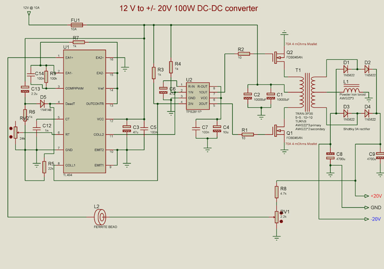
12V to +/- 20V DC Converter Circuit
A DC to DC converter circuit is designed to convert a DC voltage to another DC voltage with different levels. This specific converter transforms a +12 V DC input into a symmetrical output of +/-20 V DC. Such circuits are...
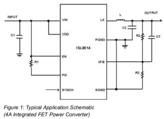
Power Supply Design Made Easy
Utilizing Integrated Switching Regulators in Power Supply Design Engineers often find themselves pondering where to begin when designing power supplies. Key decisions must be made regarding...
Integrated switching regulators are critical components in modern power supply design, offering efficient voltage conversion...