


Buck-boost-converter
#buck-boost converter
#voltage converter
#lead-acid battery
#input voltage swing
#low battery indicator
#DC-DC converter
#power management
#voltage regulation
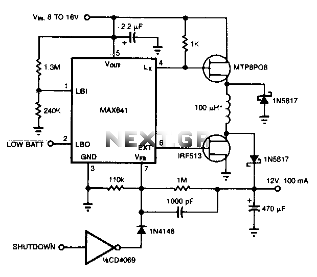
Description: This converter can accommodate wide input voltage swings, such as the 8 to 15 V range typical of a 12 V sealed lead-acid battery. The low battery output indicates when the input voltage drops below 8 V. Pulling the shutdown pin turns off the circuit.
This voltage converter is designed to operate effectively within a specified input voltage range, specifically from 8 V to 15 V, which is commonly encountered in applications involving 12 V sealed lead-acid batteries. It features a low battery output signal that activates when the input voltage falls below 8 V, providing a critical alert for battery management systems to prevent over-discharge and potential damage to the battery.
The shutdown function is implemented through a dedicated pin, which allows for the circuit to be turned off when pulled low. This feature is essential for power-saving applications, enabling the system to conserve energy when the converter is not in use or when the battery voltage is too low to maintain proper operation.
In terms of schematic representation, the converter circuit typically includes several key components: a voltage regulator, input and output capacitors, a feedback network for voltage regulation, and the shutdown control pin. The input capacitor stabilizes the voltage and filters out noise, while the output capacitor ensures a smooth output voltage. The feedback network adjusts the output voltage based on the load conditions and input variations. The shutdown control pin is connected to a switch or microcontroller output, allowing for external control of the converter's operation.
Overall, this converter is suitable for applications requiring reliable voltage regulation from lead-acid batteries while providing essential features for battery monitoring and system control.This converter can accommodate wide inputvoltage swings, such as the 8 to 15-V swing typical of a 12-V sealed lead/acid battery. The low battery output indicates when input voltage drops below 8V. Pulling shutdown turns off the circuit.
This voltage converter is designed to operate effectively within a specified input voltage range, specifically from 8 V to 15 V, which is commonly encountered in applications involving 12 V sealed lead-acid batteries. It features a low battery output signal that activates when the input voltage falls below 8 V, providing a critical alert for battery management systems to prevent over-discharge and potential damage to the battery.
The shutdown function is implemented through a dedicated pin, which allows for the circuit to be turned off when pulled low. This feature is essential for power-saving applications, enabling the system to conserve energy when the converter is not in use or when the battery voltage is too low to maintain proper operation.
In terms of schematic representation, the converter circuit typically includes several key components: a voltage regulator, input and output capacitors, a feedback network for voltage regulation, and the shutdown control pin. The input capacitor stabilizes the voltage and filters out noise, while the output capacitor ensures a smooth output voltage. The feedback network adjusts the output voltage based on the load conditions and input variations. The shutdown control pin is connected to a switch or microcontroller output, allowing for external control of the converter's operation.
Overall, this converter is suitable for applications requiring reliable voltage regulation from lead-acid batteries while providing essential features for battery monitoring and system control.This converter can accommodate wide inputvoltage swings, such as the 8 to 15-V swing typical of a 12-V sealed lead/acid battery. The low battery output indicates when input voltage drops below 8V. Pulling shutdown turns off the circuit.
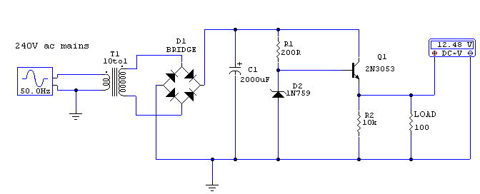
Regulated 12 Volt Supply
This circuit utilizes a 13-volt zener diode (D2) for voltage regulation. Approximately 0.7 volts are dropped across the base-emitter junction of the transistors, resulting in a higher current output of 12.3 volts. The circuit is capable of supplying loads up...
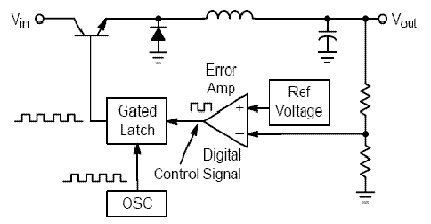
3V to 40 Volt DC Converter Circuit Schematic Diagram
Switching regulator subsystems are designed for use as DC to DC converters. The 3V to 40V DC converter circuit utilizes switching regulators, which are increasingly favored over linear regulators due to the demand for higher conversion efficiency in modern equipment...
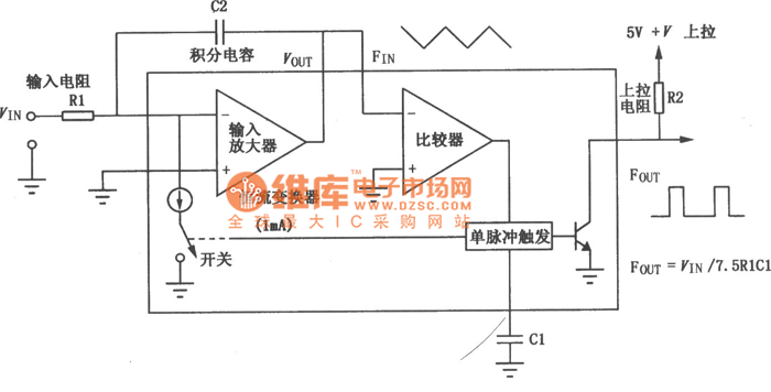
VFC62 voltage / frequencyfrequency / voltage converter circuit
The VFC62 is a voltage-to-frequency and frequency-to-voltage converter that effectively transforms analog signals into digital signals. The digital output is presented in an open collector format, where the digital pulse repetition rate is directly proportional to the amplitude of the...
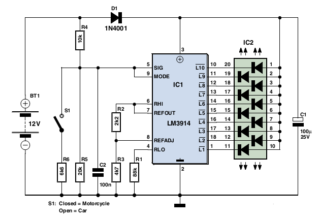
Car & Motorcycle Battery Tester
Typically, a charged lead-acid battery and a power inverter are utilized to ensure a well-organized holiday where family members can enjoy their electric and electronic devices. With rechargeable lead-acid batteries, it is often beneficial, if not essential, to determine whether...
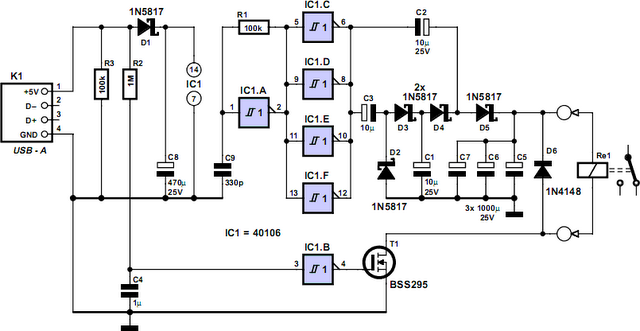
Computer Off Switch
How often does it happen that a user shuts down Windows and then forgets to turn off the computer? This circuit automates that process. After Windows is shut down, a click occurs a second later, disconnecting the PC from the...

periodic steady state analysis for dc to dc converters
Connect with Cadence technologists and peers in the Cadence Community. Stay informed about technology trends, news, and opinions through blogs, forums, and social networking.
The Cadence Community serves as a collaborative platform for professionals in the electronics design automation (EDA) field....
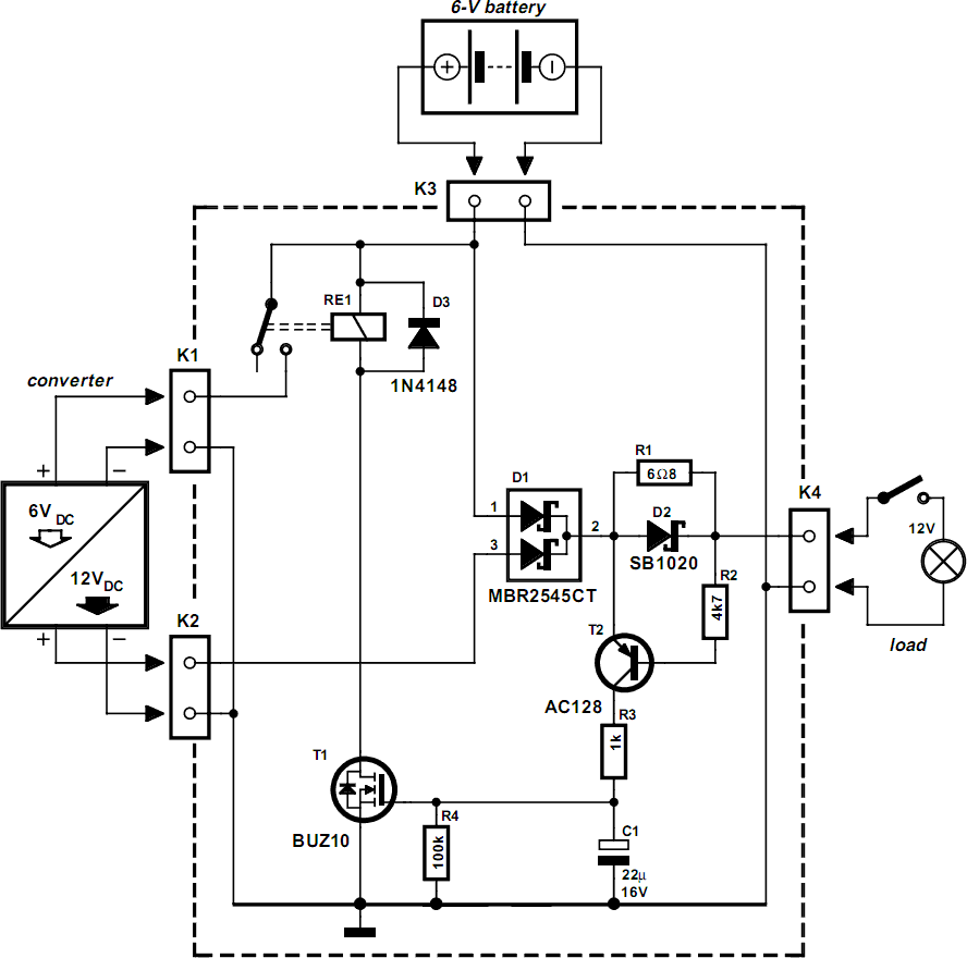
Automatic Switch For Voltage Converters
New applications for DC voltage converters, such as the LT1070, arise every day. These converters can be adapted to nearly every imaginable ratio of input and output voltages. However, all of these circuits and devices share a common shortcoming: they...
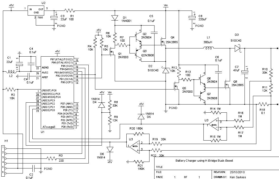
A Half Bridge Buck Boost Converter with high side N-type MOSFET
The buck-boost converter is valuable when the output and/or input voltages fluctuate significantly, necessitating the use of a buck converter at times and a boost converter at others. An example, which will be elaborated on in a future project, is...
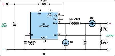
Cheap Switch-Mode DC-DC Converter
This circuit utilizes mobile phone chargers that incorporate the Motorola MC34063 switch-mode integrated circuit (IC). The output voltage can be adjusted across a broad spectrum by altering the values of the feedback resistors R1 and R2. The output voltage is...