


Buck boost converter circuit
#buck boost converter
#LTC3440
#voltage regulator
#efficient power supply
#inductor
#600mA output
#Linear Technology
#power management
#DC-DC converter
#96% efficiency
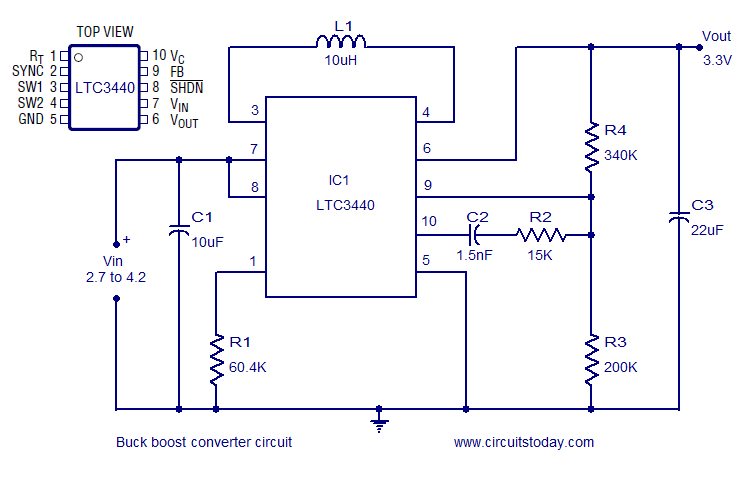
Description: A highly efficient buck-boost converter circuit is presented, utilizing the LTC3440 buck-boost regulator IC from Linear Technology. This IC requires only one inductor and achieves efficiency levels of up to 96%. For applications where the output voltage is below 4.3V, a Schottky diode is not necessary, and the IC can deliver an output current of up to 600mA. In this configuration, the IC operates as a buck-boost regulator, providing a stable 3.3V output from an input voltage range of 2.7V to 4.2V. The timing resistor, R1, determines the oscillator frequency and can be adjusted between 300kHz and 2MHz by changing its value. C1 serves as the input bypass capacitor, minimizing noise, while C3 acts as the output filter capacitor. Resistors R4 and R4 (likely a typographical error, intended to indicate two different resistors) are used to set the output voltage, and the combination of C2 and R2 is designed for frequency compensation.
The LTC3440 buck-boost converter circuit is designed for applications requiring efficient voltage regulation across a wide input voltage range. The circuit's architecture allows it to step up or step down the input voltage to maintain a consistent output of 3.3V, which is suitable for powering various electronic devices. The use of a single inductor simplifies the design and reduces component count, which can be beneficial for space-constrained applications.
The oscillator frequency, determined by resistor R1, plays a critical role in the performance of the converter. A higher frequency can lead to smaller inductor and capacitor sizes, improving the overall compactness of the circuit. However, it is essential to balance frequency and efficiency, as higher frequencies may introduce increased switching losses.
The input bypass capacitor, C1, is crucial for maintaining stable operation by filtering out high-frequency noise that may be present on the input voltage line. This helps to ensure that the LTC3440 operates within its specified parameters and enhances the reliability of the output voltage.
The output filter capacitor, C3, smooths out the voltage ripple at the output, ensuring a clean and stable 3.3V supply for the load. The output voltage setting resistors (R4) form a voltage divider that allows for precise adjustment of the output voltage level, enabling flexibility in the design for various load requirements.
The frequency compensation network, consisting of C2 and R2, is vital for maintaining stability in the feedback loop of the converter. Proper compensation ensures that the converter responds adequately to changes in load and input voltage without oscillating or becoming unstable.
This buck-boost converter circuit is ideal for battery-powered applications, portable devices, or any system where input voltage may vary widely, providing a reliable and efficient solution for voltage regulation.A very efficient buck boost converter circuit is shown here. The circuit is based on the LTC3440 buck boost regulator IC from Linear Technology. The LTC3440 requires only one inductor and provides up to 96% efficiency. There is no need of Schottky diode for applications where output voltage is less than 4. 3V and the IC can deliver up to 600mA outp ut current. In the circuit the IC is wired as a buck boost regulator providing 3. 3V output from a 2. 7 to 4. 2V input. R1 is the timing resistor which determines the oscillator frequency and it can be varied between 300 KHz to 2MHz by varying the value of R1. C1 is the input bypass capacitor for reducing noise and C3 is the output filter capacitor. Resistors R4, R4 sets the output voltage and the network consisting of C2 and R2 is meant for frequency compensation.
We aim to transmit more information by carrying articles. Please send us an E-mail to wanghuali@hqew. net within 15 days if we are involved in the problems of article content, copyright or other problems. We will delete it soon.
The LTC3440 buck-boost converter circuit is designed for applications requiring efficient voltage regulation across a wide input voltage range. The circuit's architecture allows it to step up or step down the input voltage to maintain a consistent output of 3.3V, which is suitable for powering various electronic devices. The use of a single inductor simplifies the design and reduces component count, which can be beneficial for space-constrained applications.
The oscillator frequency, determined by resistor R1, plays a critical role in the performance of the converter. A higher frequency can lead to smaller inductor and capacitor sizes, improving the overall compactness of the circuit. However, it is essential to balance frequency and efficiency, as higher frequencies may introduce increased switching losses.
The input bypass capacitor, C1, is crucial for maintaining stable operation by filtering out high-frequency noise that may be present on the input voltage line. This helps to ensure that the LTC3440 operates within its specified parameters and enhances the reliability of the output voltage.
The output filter capacitor, C3, smooths out the voltage ripple at the output, ensuring a clean and stable 3.3V supply for the load. The output voltage setting resistors (R4) form a voltage divider that allows for precise adjustment of the output voltage level, enabling flexibility in the design for various load requirements.
The frequency compensation network, consisting of C2 and R2, is vital for maintaining stability in the feedback loop of the converter. Proper compensation ensures that the converter responds adequately to changes in load and input voltage without oscillating or becoming unstable.
This buck-boost converter circuit is ideal for battery-powered applications, portable devices, or any system where input voltage may vary widely, providing a reliable and efficient solution for voltage regulation.A very efficient buck boost converter circuit is shown here. The circuit is based on the LTC3440 buck boost regulator IC from Linear Technology. The LTC3440 requires only one inductor and provides up to 96% efficiency. There is no need of Schottky diode for applications where output voltage is less than 4. 3V and the IC can deliver up to 600mA outp ut current. In the circuit the IC is wired as a buck boost regulator providing 3. 3V output from a 2. 7 to 4. 2V input. R1 is the timing resistor which determines the oscillator frequency and it can be varied between 300 KHz to 2MHz by varying the value of R1. C1 is the input bypass capacitor for reducing noise and C3 is the output filter capacitor. Resistors R4, R4 sets the output voltage and the network consisting of C2 and R2 is meant for frequency compensation.
We aim to transmit more information by carrying articles. Please send us an E-mail to wanghuali@hqew. net within 15 days if we are involved in the problems of article content, copyright or other problems. We will delete it soon.
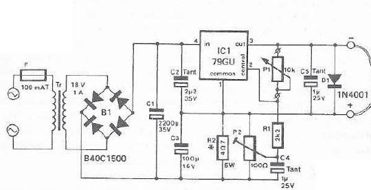
mini drill speed regulator
An integrated voltage regulator connected in reverse to a mini drill allows for speed adjustment within specific limits, maintaining a constant speed regardless of load. The electronic speed control is achieved through a voltage regulator, which can power motors requiring...
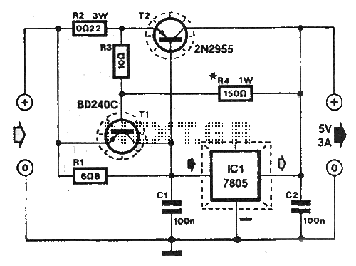
Shortcircuit protected voltage regulator
At this voltage regulator prototype the maximum current, with output shortcircuited it was only 0.5 A, so no overheating occurred. In this DC voltage regulator circuit, T1 is for current limitation. As soon as the voltage on the R2 +...
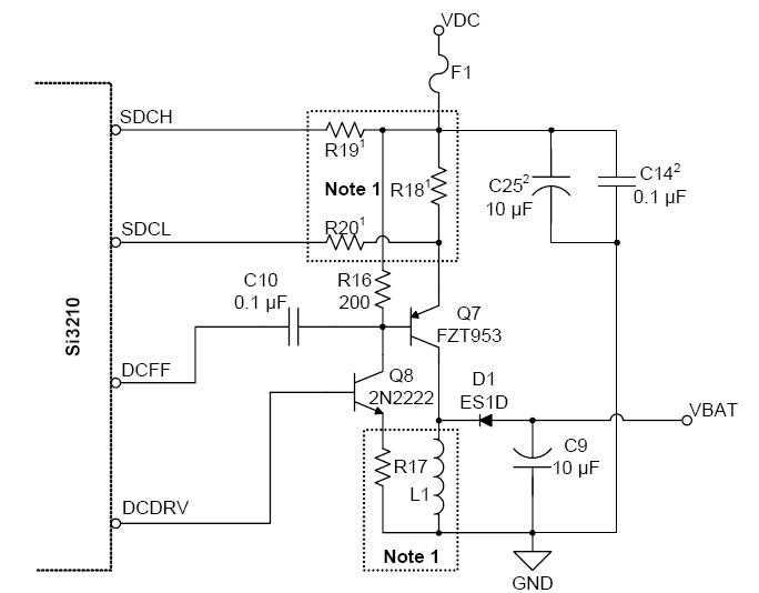
chasing an elusive bug around
Since the last update, significant efforts have been directed towards debugging the board. Multiple issues have been identified in the implementation of the DC-DC converter circuitry. However, sufficient evidence has been collected regarding the bug, indicating that it is neither...
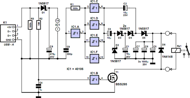
Computer Off Switch
How often does it happen that a user shuts down Windows and then forgets to turn off the computer? This circuit automates that process. After Windows is shut down, a click occurs a second later, disconnecting the PC from the...
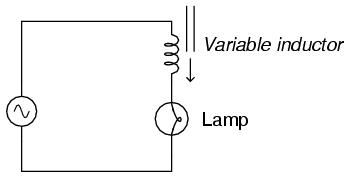
Variable inductor
Wind hundreds of turns of magnet wire around a paper tube. Connect this homemade inductor in series with an AC power supply and a lamp to create a circuit. When the tube is empty, the lamp should shine brightly. When...
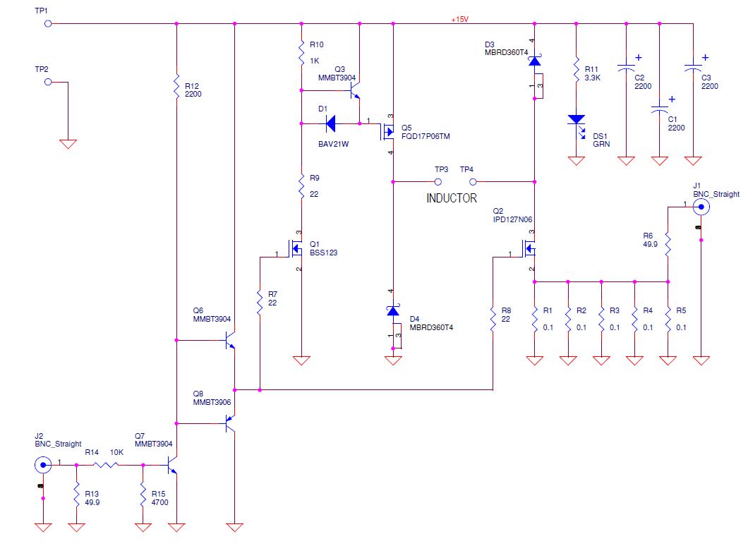
Inductor saturation tester alternative route to dump the excess energy
Yes, it does charge the inductor again. Diodes are beneficial as they do not charge the inductor back but dissipate a significant amount of instantaneous power due to the forward voltage drop. One approach would be to monitor the current...
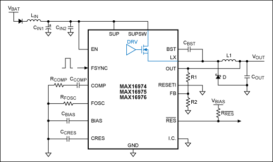
Layout Guidelines for the MAX16974/MAX16975/MAX16976 DC-DC Converters
Optimize the layout of the MAX16974/MAX16975/MAX16976 high-performance DC-DC converters, which are standard buck controllers designed for automotive applications.
The MAX16974, MAX16975, and MAX16976 are advanced DC-DC buck converters specifically tailored for automotive environments. These devices are engineered to deliver high efficiency...
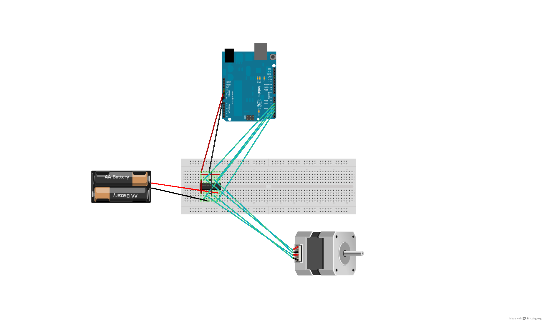
Voltage regulator or resistors to change voltages for motors
After conducting some research, it was found that voltage can be adjusted using either a voltage regulator chip or resistors. Several scenarios require reducing the voltage for motors, prompting a question about the appropriate method for each application. An H-Bridge...
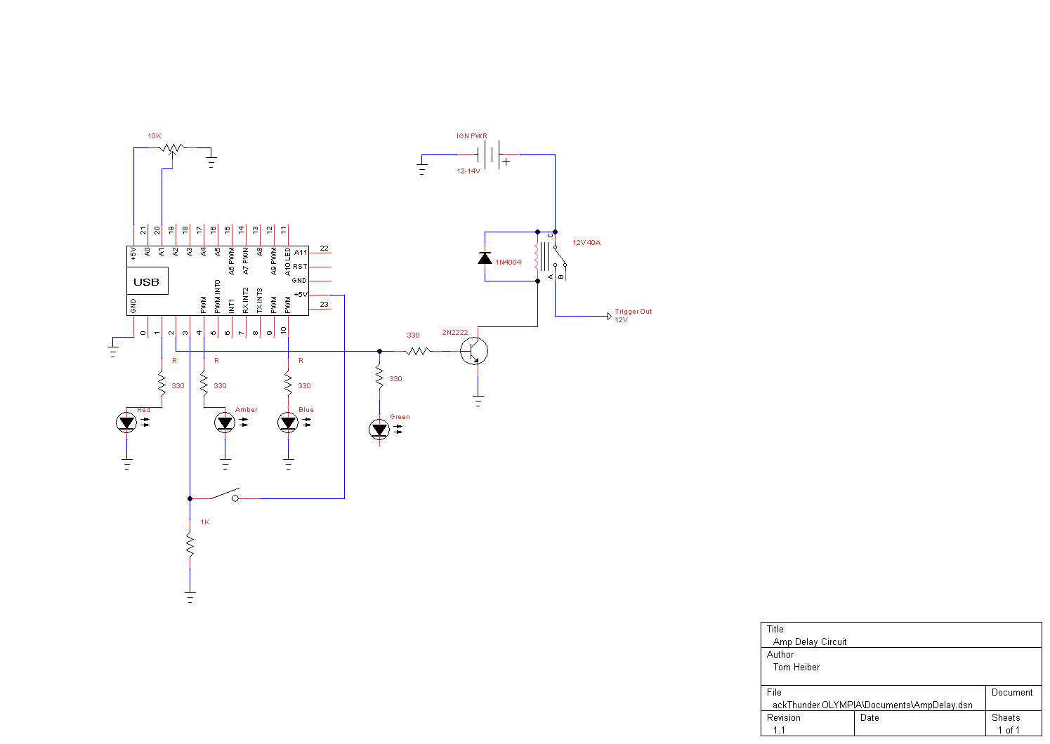
smart amp delay
This system is designed as a Windows service that detects various power events, including Suspend, Hibernate, Reboot, and Shutdown. It can send appropriate responses to a control circuit, specifically a Heartbeat or Kill signal. The trigger mechanism is also regulated...