


buck converter design demystified
#buck converter
#stepdown converter
#voltage regulation
#power electronics
#DC-DC converter
#switching regulator
#circuit design
#energy efficiency
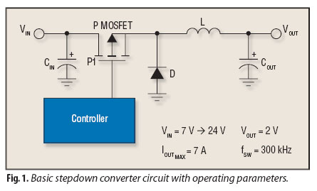
Description: Although step-down converters, commonly known as buck converters, are highly popular, the guidelines and calculations that facilitate their design can be challenging to locate.
Buck converters are a type of DC-DC converter that efficiently reduce a higher input voltage to a lower output voltage while maintaining a high level of efficiency. They are widely used in various applications, including power supplies for microcontrollers, battery chargers, and LED drivers. The fundamental operation of a buck converter involves the use of a switch (typically a transistor), a diode, an inductor, and a capacitor.
The switching element alternates between the on and off states, controlling the energy transferred to the inductor. When the switch is closed, current flows through the inductor, storing energy in its magnetic field. When the switch opens, the inductor releases the stored energy to the output load through the diode. The capacitor smooths the output voltage, reducing ripple and providing a stable voltage to the load.
Key parameters to consider in buck converter design include the input voltage range, output voltage, output current, switching frequency, and efficiency. The inductor value can be calculated based on the desired output current ripple and the switching frequency. Similarly, the output capacitor value is determined by the acceptable voltage ripple at the output and the load transient response.
To optimize performance, it is essential to select components that can handle the required current and voltage ratings, and to implement proper layout techniques to minimize parasitic inductance and resistance. Additionally, feedback control mechanisms are often employed to maintain output voltage regulation under varying load conditions.
Overall, understanding the operational principles and design considerations of buck converters is crucial for engineers looking to implement these devices in efficient power management solutions.Though stepdown converters - buck converters - are extremely popular, the rules of thumb and calculations that speed their design can be hard to find..
Buck converters are a type of DC-DC converter that efficiently reduce a higher input voltage to a lower output voltage while maintaining a high level of efficiency. They are widely used in various applications, including power supplies for microcontrollers, battery chargers, and LED drivers. The fundamental operation of a buck converter involves the use of a switch (typically a transistor), a diode, an inductor, and a capacitor.
The switching element alternates between the on and off states, controlling the energy transferred to the inductor. When the switch is closed, current flows through the inductor, storing energy in its magnetic field. When the switch opens, the inductor releases the stored energy to the output load through the diode. The capacitor smooths the output voltage, reducing ripple and providing a stable voltage to the load.
Key parameters to consider in buck converter design include the input voltage range, output voltage, output current, switching frequency, and efficiency. The inductor value can be calculated based on the desired output current ripple and the switching frequency. Similarly, the output capacitor value is determined by the acceptable voltage ripple at the output and the load transient response.
To optimize performance, it is essential to select components that can handle the required current and voltage ratings, and to implement proper layout techniques to minimize parasitic inductance and resistance. Additionally, feedback control mechanisms are often employed to maintain output voltage regulation under varying load conditions.
Overall, understanding the operational principles and design considerations of buck converters is crucial for engineers looking to implement these devices in efficient power management solutions.Though stepdown converters - buck converters - are extremely popular, the rules of thumb and calculations that speed their design can be hard to find..
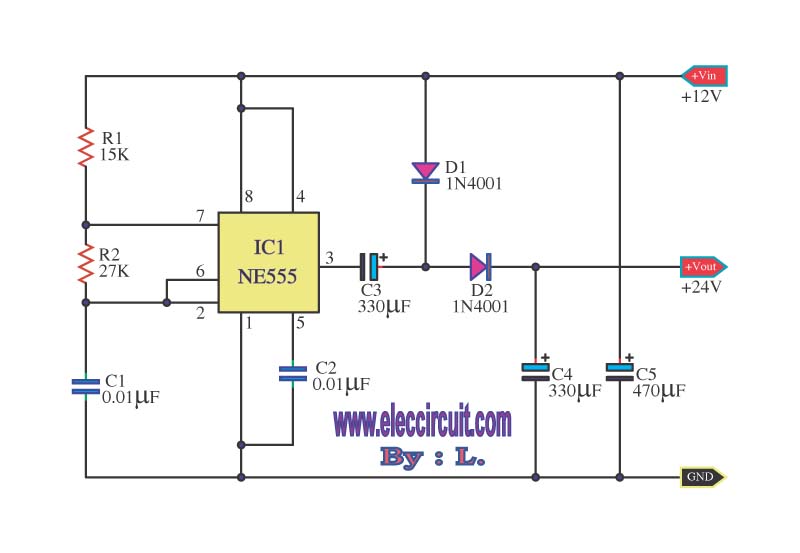
The many DC to DC converters using IC-555
This is a simple voltage doubler circuit that converts 12V DC into 24V DC. It utilizes the popular NE555 timer IC along with a few additional components. The circuit can provide approximately 50mA of current, making it suitable for low-current...
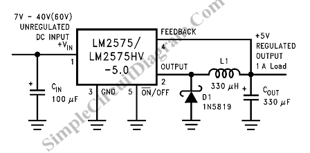
5V Switching Regulator Very Simple Circuit
Switching Regulator for High Power Efficiency. When it is necessary to convert a high voltage to a significantly lower voltage, a switching regulator is the optimal choice.
A switching regulator is an essential component in modern power management systems, particularly when...
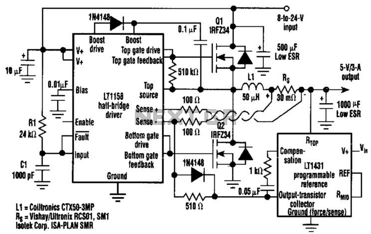
3A Dc-Dc Converter Needs No Heatsink Circuit
This regulator achieves 90% efficiency with a 12-V input and a 5-V output. It utilizes the LT1158 and LT1431 components from Linear Technology, Inc. High efficiency is accomplished by synchronously switching two power MOSFETs in a step-down switching regulator. The...
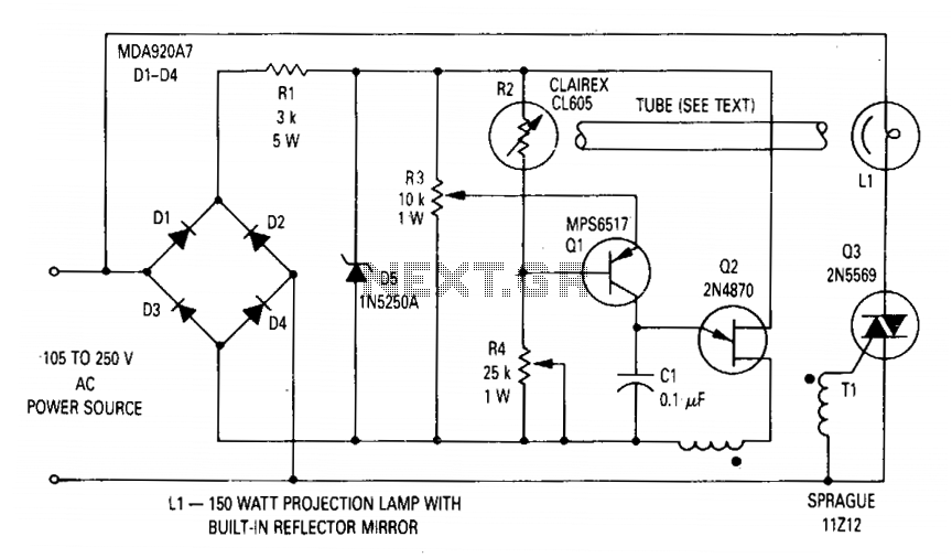
Voltage regulator for projection lamp
The circuit regulates the RMS output voltage across a load, specifically a projection lamp, to 100 volts ±2% for input voltages ranging from 105 to 250 volts AC. This regulation is achieved by indirectly sensing the light output of lamp...
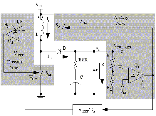
A user friendly boost DC DC converter topology
In battery-powered applications such as cell phones, PDAs, and digital cameras, an integrated DC-DC converter circuit solution provides multiple advantages regarding cost, size, and design complexity. A significant challenge in achieving a fully integrated solution is designing the frequency compensation...
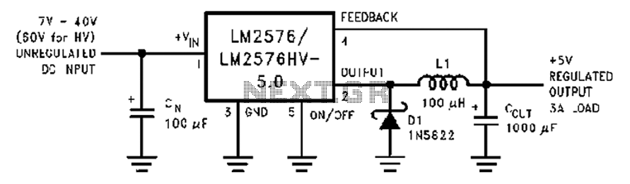
A wide range of 7 ~ 40V turn 5VDC-DC step-down circuit diagram
A wide range of 7 to 40V DC-DC step-down circuit that converts input voltage to 5V.
This circuit operates as a buck converter, designed to efficiently reduce a higher DC voltage (ranging from 7V to 40V) to a stable output of...
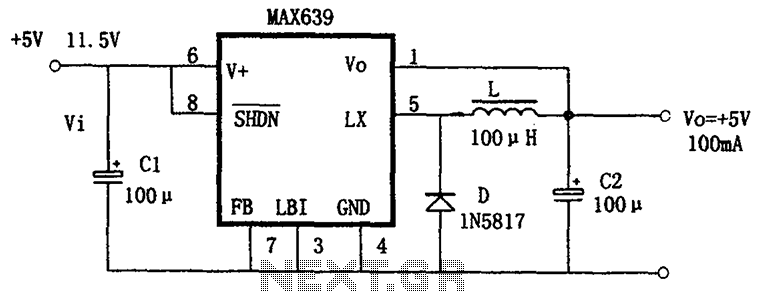
Buck power conversion by the MAX639 + 5V fixed output
The circuit is based on the MAX639, which is a high-efficiency, step-down DC/DC converter. It operates with an input voltage range of 5.5V to 11.5V, providing a fixed output voltage of +5V or an adjustable voltage. The output current capability...
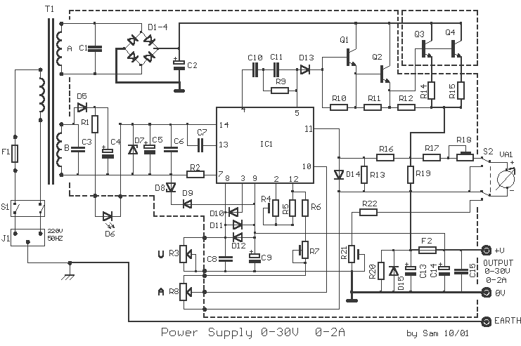
Power Supply 0-30V / 0-2A
The basic requirements for a laboratory power supply are to provide the necessary voltages and currents with low output resistance, low noise, minimal ripple, and good stabilization. These requirements are addressed within the circuit design. Many power supplies incorporate electronic...
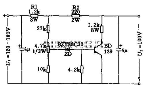
100v / 10ma regulator circuit
The circuit features no-load and short circuit protection mechanisms. To accommodate short circuit conditions, it is necessary to increase resistors R1 and R2 to allow for power dissipation; for example, R1 can be set to 1.2kΩ with a power rating...