


Car 12V to +-20V DC converter
#DC converter
#12V to 20V
#push-pull design
#audio amplifier
#high current
#power supply
#car electronics
#voltage conversion
#flux walking
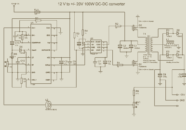
Description: The limitation of car supply voltage (12V) forces to convert the voltages to higher in order to power audio amplifiers. This supply is intended for two channels with 50W max each (of course it depends on the amplifier used). Though it can be easily scaled up or the voltages changed to obtain different values. It is a classic push-pull design, taking care to obtain best symmetry (to avoid flux walking). Keep in mind that this circuit will adsorb many amperes (around 10A) so take care to reinforce power tracks with lots of solder and use heavy wires from the battery or the voltage will drop too much at the input. More: In fact the max audio power x speaker (with 4 ohm impedance) using 12V is (Vsupply+ - Vsupply-)^2/(8*impedance) 12^2/32 = 4.5Watts per channel, that is laughable... For powering correctly an amplifier the best is to use a symmetric supply with a high voltage differential. for example +20 - -20 = 40Volts in fact 40^2/32 = 50 Watts per channel that is respectable. The transformer must be designed to reduce skin effect, it can be done using several insulated magnet wire single wires soldered together but conducting separately. The regulation is done both by the transformer turn ratio and varying the duty cycle. In my case i used 5+5, 10+10 turns obtaining a step up ratio of 2 (12->24) and downregulating the voltage to 20 via duty cycle dynamic adjust performed by the PWM controller TL494. The step-up ratio has to be a little higher to overcome diode losses, winding resistance and so on and input voltage drop due to wire resistance from battery to converter. The transformer must be of correct size in order to carry the power needed, on the net there are many charts showing the power in function of frequency and core size for a given topology. My transformer size is 33.5 mm length, 30.0 height and 13mm width with a cross section area of 1.25cm^2, good for powers around 150W at 50khz. The windings, especially the primary must be heavy gauged, but instead of using a single wire it is better to use multiple wires in parallel each insulated from the other except at the ends. This will reduce resistance increase due to skin effect. The primary and secondary windings are centertapped, this means that you have to wind 5 turns, centertap and 5 windings again. The same goes for the secondary, 10 turns, centertap and 10 turns again. The important thing is that the transformer MUST not have air gaps or the leakage inductance will throw spikes on the switches overheating them and giving a voltage higher than expected by turn ratio prediction, so if your voltage output (at fully duty cycle) is higher than Vin*N2/N1 - Vdrop diode, your transformer has gap (of course permit me saying you that you are BLIND if you miss it), and this is accompanied with a drastic efficiency reduction. Use non-gapped E cores or toroids (ferrite). For rectification i preferred to use shottky diodes since they have low forward voltage drop, and are incredibly fast. I used the cheap 1N5822, the best alternative for low voltage converters (3A for current capability). The output capacitors are 4700uF 25V, not very big, since at high frequency the voltage ripple is most due to internal cap ESR fortunately general purpose lytics have enough low esr for a small ripple (some tens of millivolts). Also at high duty cycle they are fed almost with pure DC, giving small ripple. The filter inductor on the secondary centertap further increases the ripple and helps the regulation in asymmetrical transients. I used d2pak 70V 80A 0.004 ohms ultrafets (Fairchild semiconductor), very expensive and hard to find. In principle any fet will work, but the lower the on-resistance, the lower the on-state conduction losses, the lower the heat produced on the fets, the higher efficiency and smaller the heatsinks needed. With this fets i am able to run the fets with small heatsinks and without fan at full rated power (100W) with an efficiency of 82% and perceptible heating and with small heating at 120W (some degrees) (the core starts to saturate and the efficiency is a bit lower, around 75%) Try to use the lowest resistance mosfet you can put your dirty hand :-) on or the efficiency will be lower than rated and you will need even a small fan. The fet driver i used is the TPS2811P, from Texas instruments, rated for 2A peak and 200ns. Is important that the gate drive is optimized for minimal inductance or the switching losses will be higher and you risk noise coupling from other sources. Personally i think that twisted pair wires (gate and ground/source) are the best to keep the inductance small. Place the gate drive resistor near the Mosfet, not near the IC. This supply given me up to 85% efficiency (sometimes even 90% at some loads) with an input of 12V because i observed all these tricks to keep it functional and efficient. An o-scope would be useful, to watch the ripple and gate signals (watching for overshoots), but if you follow these guidelines you will avoid these problems. The cross regulation is good but keep in mind that only the positive output is fully regulated, and the negative only follows it. Place a small load between the negative rail and ground (a 3mm led with a 4.7Kohm resistor) to avoid the negative rail getting lower then -20V. If the load is asymmetric you can have two cases: -More load on positive rail-> no problems, the negative rail can go lower than -20V, but it is not a real issue for an audio amplifier. -More load on negative rail-> voltage drop on negative rail (to ground) especially if the load is only on the negative rail.
The circuit described is a power supply designed to convert a 12V automotive supply to a higher voltage suitable for powering audio amplifiers, utilizing a classic push-pull topology. The power supply is intended to deliver a maximum of 50W per channel across two channels. To achieve the necessary voltage increase, a transformer with a specific turn ratio is employed, in this case, a step-up ratio of 2, allowing conversion from 12V to approximately 24V, which is then regulated down to 20V using a PWM controller (TL494).
The transformer design is critical, as it must minimize skin effect and avoid air gaps that could lead to inefficiencies and overheating. The transformer is specified with dimensions conducive to handling approximately 150W at a frequency of 50 kHz, with multiple insulated wires used for the primary winding to reduce resistance. The centertap configuration allows for balanced operation, and special attention is given to the winding technique to ensure proper functionality.
For rectification, Schottky diodes (1N5822) are utilized due to their low forward voltage drop and fast switching capabilities. The output capacitors are selected for their low equivalent series resistance (ESR), which is essential to minimize voltage ripple at high frequencies. The circuit also incorporates a filter inductor to assist in maintaining voltage stability during transient conditions.
The MOSFETs used in the switching stage are selected for their low on-resistance to enhance efficiency and minimize heat generation, with a focus on maintaining high performance without the need for active cooling. The driver circuit (TPS2811P) is optimized for minimal inductance to reduce switching losses, and careful layout considerations are made to ensure signal integrity.
Cross regulation is implemented, with the positive rail being fully regulated while the negative rail tracks the positive output. A small load is recommended on the negative rail to maintain voltage levels during operation, ensuring reliable performance under varying load conditions. Overall, the design emphasizes efficiency, reliability, and performance suitable for audio amplification applications.The limitation of car supply voltage (12V) forces to convert the voltages to higher in order to power audio amplifiers. This supply is intended for two channels with 50W max each (of course it depends on the amplifier used).
Though it can be easily scaled up or the voltages changed to obtain different values. It is a classic push-pull design , taking care to obtain best symmetry (to avoid flux walking). Keep in mind that this circuit will adsorb many amperes (around 10A) so take care to reinforce power tracks with lots of solder and use heavy wires from the battery or the voltage will drop too much at the input. In fact the max audio power x speaker (with 4 ohm impedance) using 12V is (Vsupply+ - Vsupply-)^2/(8*impedance) 12^2/32 = 4.5Watts per channel, that is laughable... For powering correctly an amplifier the best is to use a symmetric supply with a high voltage differential.
for example +20 - -20 = 40Volts in fact 40^2/32 = 50 Watts per channel that is respectable. The transformer must be designed to reduce skin effect, it can be done using several insulated magnet wire single wires soldered together but conducting separately. The regulation is done both by the transformer turn ratio and varying the duty cycle. In my case i used 5+5 , 10+10 turns obtaining a step up ratio of 2 (12->24) and downregulating the voltage to 20 via duty cycle dynamic adjust performed by the PWM controller TL494.
The step-up ratio has to be a little higher to overcome diode losses, winding resistance and so on and input voltage drop due to wire resistance from battery to converter. The transformer must be of correct size in order to carry the power needed, on the net there are many charts showing the power in function of frequency and core size for a given topology.
My transformer size is 33.5 mm lenght, 30.0 height and 13mm width with a cross section area of 1,25cm^2, good for powers around 150W at 50khz. The windings , especially the primary must be heavy gauged, but instead of using a single wire it is better to use multiple wires in parallel each insulated from the other except at the ends.
This will reduce resistance increase due to skin effect. The primary and secondary windings are centertapped, this means that you have to wind 5 turns, centertap and 5 windings again. The same goes for the secondary, 10 turns, centertap and 10 turns again. The important thing is that the transformer MUST not have air gaps or the leakage inductance will throw spikes on the switches overheating them and giving a voltage higher than expected by turn ratio prediction, so if your voltage output (at fully duty cycle) is higher than Vin*N2/N1 - Vdrop diode, your transformer has gap (of course permit me saying you that you are BLIND if you miss it), and this is accompanied with a drastical efficiency reduction.
Use non-gapped E cores or toroids (ferrite). For rectification i preferred to use shottky diodes since they have low forward voltage drop, and are incredibly fast. I used the cheap 1N5822, the best alternative for low voltage converters (3A for current capability).
The output capacitors are 4700uF 25V, not very big, since at high frequency the voltage ripple is most due to internal cap ESR fortunately general purpose lytics have enough low esr for a small ripple (some tens of millivolts). Also at high duty cycle they are feed almost with pure DC, giving small ripple. The filter inductor on the secondary centertap furter increases the ripple and helps the regulation in asymmetrical transients.
I used d2pak 70V 80A 0.004 ohms ultrafets (Fairchind semiconductor), very expensive and hard to find. In principle any fet will work, but the lower the on-resistance, the lower the on-state conduction losses, the lower the heat produced on the fets, the higher efficiency and smaller the heatsinks needed.
With this fets i am able to run the fets with small heatsinks and without fan at full rated power (100W) with an efficiency of 82% and perceptible heating and with small heating at 120W (some degrees) (the core starts to saturate and the efficiency is a bit lower, around 75%) Try to use the lowest resistance mosfet you can put your dirty hand :-) on or the efficiency will be lower than rated and you will need even a small fan. The fet driver i used is the TPS2811P, from Texas instruments, rated for 2A peak and 200ns. Is important that the gate drive is optimized for minimal inductance or the switching losses will be higher and you risk noise coupling from other sources.
Personally i think that twisted pair wires (gate and ground/source) are the best to keep the inductance small. Place the gate drive resistor near the Mosfet, not near the IC. This supply given me up to 85% efficiency (sometimes even 90% at some loads) with an input of 12V because i observed all these tricks to keep it functional and efficient.
An o-scope would be useful, to watch the ripple and gate signals (watching for overshoots), but if you follow these guidelines you will avoid these problems. The cross regulation is good but keep in mind that only the positive output is fully regulated, and the negative only follows it.
Place a small load between the negative rail and ground (a 3mm led with a 4.7Kohm resistor) to avoid the negative rail getting lower then -20V. If the load is asymmetric you can have two cases: -More load on positive rail-> no problems, the negative rail can go lower than -20V, but it is not a real issue for an audio amplifier.
-More load on negative rail-> voltage drop on negative rail (to ground) especially if the load is only on the negative rail.
The circuit described is a power supply designed to convert a 12V automotive supply to a higher voltage suitable for powering audio amplifiers, utilizing a classic push-pull topology. The power supply is intended to deliver a maximum of 50W per channel across two channels. To achieve the necessary voltage increase, a transformer with a specific turn ratio is employed, in this case, a step-up ratio of 2, allowing conversion from 12V to approximately 24V, which is then regulated down to 20V using a PWM controller (TL494).
The transformer design is critical, as it must minimize skin effect and avoid air gaps that could lead to inefficiencies and overheating. The transformer is specified with dimensions conducive to handling approximately 150W at a frequency of 50 kHz, with multiple insulated wires used for the primary winding to reduce resistance. The centertap configuration allows for balanced operation, and special attention is given to the winding technique to ensure proper functionality.
For rectification, Schottky diodes (1N5822) are utilized due to their low forward voltage drop and fast switching capabilities. The output capacitors are selected for their low equivalent series resistance (ESR), which is essential to minimize voltage ripple at high frequencies. The circuit also incorporates a filter inductor to assist in maintaining voltage stability during transient conditions.
The MOSFETs used in the switching stage are selected for their low on-resistance to enhance efficiency and minimize heat generation, with a focus on maintaining high performance without the need for active cooling. The driver circuit (TPS2811P) is optimized for minimal inductance to reduce switching losses, and careful layout considerations are made to ensure signal integrity.
Cross regulation is implemented, with the positive rail being fully regulated while the negative rail tracks the positive output. A small load is recommended on the negative rail to maintain voltage levels during operation, ensuring reliable performance under varying load conditions. Overall, the design emphasizes efficiency, reliability, and performance suitable for audio amplification applications.The limitation of car supply voltage (12V) forces to convert the voltages to higher in order to power audio amplifiers. This supply is intended for two channels with 50W max each (of course it depends on the amplifier used).
Though it can be easily scaled up or the voltages changed to obtain different values. It is a classic push-pull design , taking care to obtain best symmetry (to avoid flux walking). Keep in mind that this circuit will adsorb many amperes (around 10A) so take care to reinforce power tracks with lots of solder and use heavy wires from the battery or the voltage will drop too much at the input. In fact the max audio power x speaker (with 4 ohm impedance) using 12V is (Vsupply+ - Vsupply-)^2/(8*impedance) 12^2/32 = 4.5Watts per channel, that is laughable... For powering correctly an amplifier the best is to use a symmetric supply with a high voltage differential.
for example +20 - -20 = 40Volts in fact 40^2/32 = 50 Watts per channel that is respectable. The transformer must be designed to reduce skin effect, it can be done using several insulated magnet wire single wires soldered together but conducting separately. The regulation is done both by the transformer turn ratio and varying the duty cycle. In my case i used 5+5 , 10+10 turns obtaining a step up ratio of 2 (12->24) and downregulating the voltage to 20 via duty cycle dynamic adjust performed by the PWM controller TL494.
The step-up ratio has to be a little higher to overcome diode losses, winding resistance and so on and input voltage drop due to wire resistance from battery to converter. The transformer must be of correct size in order to carry the power needed, on the net there are many charts showing the power in function of frequency and core size for a given topology.
My transformer size is 33.5 mm lenght, 30.0 height and 13mm width with a cross section area of 1,25cm^2, good for powers around 150W at 50khz. The windings , especially the primary must be heavy gauged, but instead of using a single wire it is better to use multiple wires in parallel each insulated from the other except at the ends.
This will reduce resistance increase due to skin effect. The primary and secondary windings are centertapped, this means that you have to wind 5 turns, centertap and 5 windings again. The same goes for the secondary, 10 turns, centertap and 10 turns again. The important thing is that the transformer MUST not have air gaps or the leakage inductance will throw spikes on the switches overheating them and giving a voltage higher than expected by turn ratio prediction, so if your voltage output (at fully duty cycle) is higher than Vin*N2/N1 - Vdrop diode, your transformer has gap (of course permit me saying you that you are BLIND if you miss it), and this is accompanied with a drastical efficiency reduction.
Use non-gapped E cores or toroids (ferrite). For rectification i preferred to use shottky diodes since they have low forward voltage drop, and are incredibly fast. I used the cheap 1N5822, the best alternative for low voltage converters (3A for current capability).
The output capacitors are 4700uF 25V, not very big, since at high frequency the voltage ripple is most due to internal cap ESR fortunately general purpose lytics have enough low esr for a small ripple (some tens of millivolts). Also at high duty cycle they are feed almost with pure DC, giving small ripple. The filter inductor on the secondary centertap furter increases the ripple and helps the regulation in asymmetrical transients.
I used d2pak 70V 80A 0.004 ohms ultrafets (Fairchind semiconductor), very expensive and hard to find. In principle any fet will work, but the lower the on-resistance, the lower the on-state conduction losses, the lower the heat produced on the fets, the higher efficiency and smaller the heatsinks needed.
With this fets i am able to run the fets with small heatsinks and without fan at full rated power (100W) with an efficiency of 82% and perceptible heating and with small heating at 120W (some degrees) (the core starts to saturate and the efficiency is a bit lower, around 75%) Try to use the lowest resistance mosfet you can put your dirty hand :-) on or the efficiency will be lower than rated and you will need even a small fan. The fet driver i used is the TPS2811P, from Texas instruments, rated for 2A peak and 200ns. Is important that the gate drive is optimized for minimal inductance or the switching losses will be higher and you risk noise coupling from other sources.
Personally i think that twisted pair wires (gate and ground/source) are the best to keep the inductance small. Place the gate drive resistor near the Mosfet, not near the IC. This supply given me up to 85% efficiency (sometimes even 90% at some loads) with an input of 12V because i observed all these tricks to keep it functional and efficient.
An o-scope would be useful, to watch the ripple and gate signals (watching for overshoots), but if you follow these guidelines you will avoid these problems. The cross regulation is good but keep in mind that only the positive output is fully regulated, and the negative only follows it.
Place a small load between the negative rail and ground (a 3mm led with a 4.7Kohm resistor) to avoid the negative rail getting lower then -20V. If the load is asymmetric you can have two cases: -More load on positive rail-> no problems, the negative rail can go lower than -20V, but it is not a real issue for an audio amplifier.
-More load on negative rail-> voltage drop on negative rail (to ground) especially if the load is only on the negative rail.
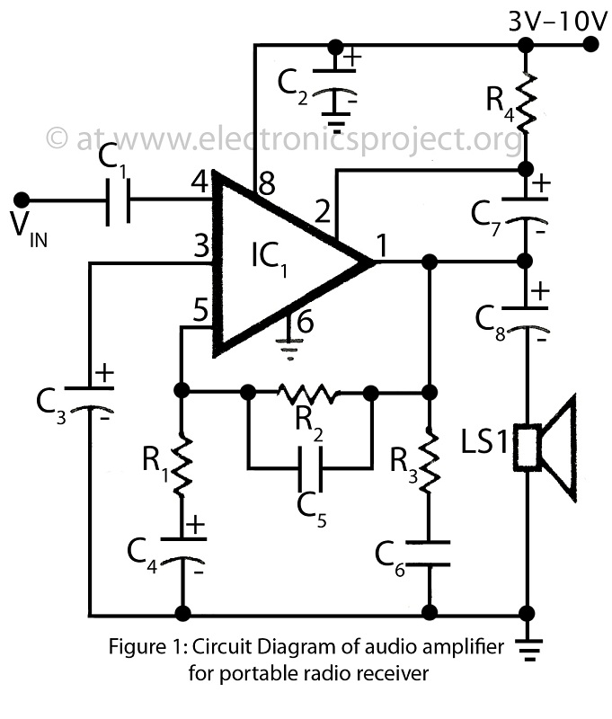
Audio amplifier for portable radio receiver
This is a simple audio amplifier circuit built around the BEL1895 1W audio amplifier integrated circuit (IC). This circuit serves as an alternative to more complex audio amplifier circuits designed for portable radio receivers. It does not require a driver...
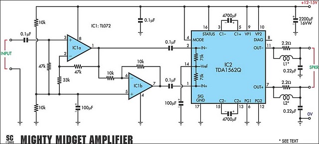
36 Watt Audio Power Amplifier Using TDA1562Q circuit
It is based on a Philips class-H audio amplifier IC and can deliver 36W RMS or 70W music power, all from a 13.8V supply. The Mighty Midget Amplifier can provide approximately 36W RMS continuous power into a 4-ohm load when...
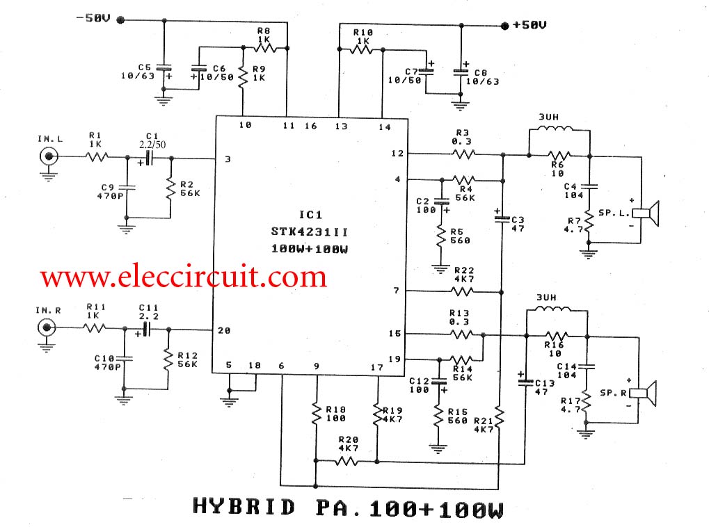
2 channel 100W min AF Power Amplifier STK4231II
To create a 100-watt OCL audio amplifier circuit, consider using this design. It incorporates the STK4231 integrated circuit, which is a compact and cost-effective solution. The STK4231 is a hybrid IC from Sanyo, belonging to the STK4201II series, capable of...
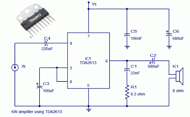
Reliable 6 Watt Hi Fi Audio Amplifier Using TDA2613
A 6-watt audio amplifier circuit utilizing the TDA2613 integrated circuit is presented. The TDA2613, produced by Philips Semiconductors, is a high-fidelity audio amplifier IC. This component is designed to be click-proof when switched on or off, resistant to short circuits,...
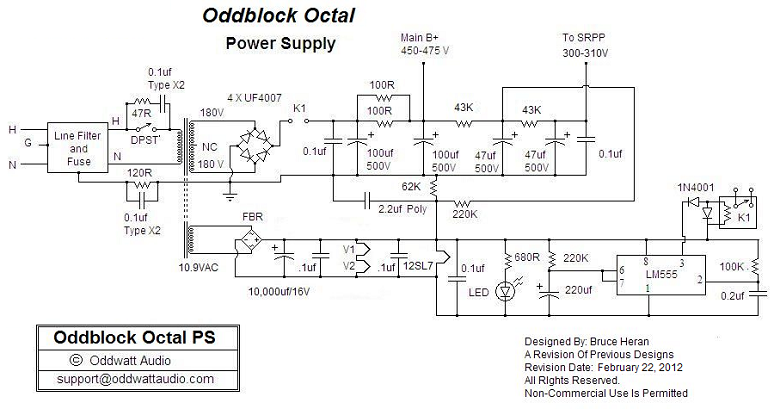
OddWatt Audio 5751 SRPP / KT88 Push-Pull Monoblock Tube Amplifier Kits
One of the advantages of hosting a hobby website is the opportunity to connect with individuals via email who share similar interests. Since posting Bruce's initial OddWatt project on the site, communication has occurred with numerous DIY hobbyists who have...
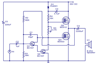
10 Watts Mosfet Audio Amplifier
This is a 10W MOSFET audio amplifier circuit that operates from a single power source. Single rail configurations are seldom used in Class B power amplifiers; however, they are suitable for low-power applications like this one. This circuit design is...
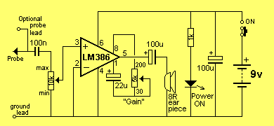
Audio Signal Testing amplifier
This mini audio amplifier will test the audio stages in amplifiers such as the front end of FM bugs. You can also use it on lots of our other projects as well as the output stages of radios. It is...
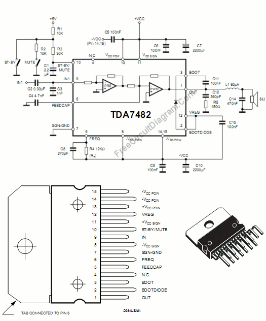
Audio Single Chip 25 Watt Mono Class-D Audio Power Amplifier Circuit
This class-D audio amplifier is suitable for TV and home stereo systems. The TDA7882 integrated circuit (IC) provides a class-D audio amplifier solution. Since this IC has a single channel output, two units are required for stereo applications. The power...
5.8 Watt Audio Power Amplifier circuit
This circuit utilizes the TA7222AP to amplify audio signals. The cost is only $0.99, and it can provide 5.8 watts with muting control. The power supply can be in the range of 8-12 VDC, making it suitable for applications such...