


Converter for producing a fixed AC from variable AC
#AC converter
#voltage regulation
#household appliances
#industrial application
#fixed AC output
#variable AC input
#power conversion
#load protection
#voltage stabilization
#electrical safety

Description: For household or industrial applications, a fixed AC voltage input is essential. Utilizing variable AC voltage for standard equipment such as lamps, fans, and televisions can severely damage these devices. Consequently, an efficient conversion system is necessary to operate these loads. The initial step involves converting variable AC to fixed DC. A power converter, situated between the generator and the grid, transforms variable-frequency AC into fixed DC and subsequently into fixed AC. This document focuses on a small-scale conversion system using readily available devices. It presents a low-cost variable AC to fixed AC system, including construction details and descriptions of various components. The objectives of this project include converting variable AC input to fixed DC output through an electronic converter circuit, simulating the circuit with PSpice, analyzing performance parameters of the designed circuitry, and establishing specific aims for the objectives. The design is divided into smaller components: generation of variable alternating current, transformation of variable frequency alternating current to fixed direct current, simulation of the generation circuit using electrical simulation software PSpice, and observation of the output. The design also encompasses the converter, filtering section, transformer, rectifier, capacitor input filter, and inverter sections, along with schematic diagrams and performance analyses of the rectifier and capacitor input filter circuits.
The rectifier circuit's performance analysis shows an input voltage (Vin) of 100.01V and an output voltage (Vout) of 98.975V, resulting in an efficiency of 81%. The ripple factor (FF) is 1.11, and the rectifier factor (RF) is 0.482, indicating a 48.2% rectification efficiency with a power factor (PF) of 0.707. In the inverter section, the supply voltage (Vs) is 85V with a resistance (R) of 100Ω, yielding an output power (Po) of 72.25W and a total harmonic distortion (THD) of 48.41%. The load power is 69.372W, and the fundamental output power is 58.568W, with the volt-ampere (Va) calculated at 69.364 volt-amperes and a power factor of 1.
A high-value capacitor is utilized, resulting in a significant charging time constant. The analog multiplier in the simulation can be substituted with digital integrated circuits such as AD633 or ADL5390, which, however, have milliwatt power ratings. As the conversion system remains continuously connected to the supply, there is a risk of overheating the MOSFETs, which could lead to component failure. This document aims to provide a comprehensive overview of the various sections of the conversion system, facilitating a foundational understanding of its construction and operational details. Theoretical descriptions are provided, followed by constructional details, enabling interested parties to further develop the system in the future. References include works by Muhammad H. Rasid and Joseph Vithayathil, which serve as foundational texts in power electronics.For household or industrial application purpose, we are bound to use fixed ac voltage input. If we try to use this variable ac voltage as input to our regular usage machinery, such as lamps, fans, TV etc. then it would cause severe damage to our instruments. However, those facts of these machines necessitate efficient conversion system to operate their loads.
So it is important firstly to convert this variable ac to a fixed dc. The power converter, positioned between the generator and the grid, transforms the variable-frequency ac to fixed dc and then to fixed ac. The total power output of the generator is combined by the converter (total conversion). Our thesis concerns a small range of this conversion system using available devices. In this thesis we have presented a low cost variable ac to fixed ac system with construction and details description of various parts.
Objectives The objectives of this effort are-To convert variable ac input to fixed dc output through electronic converter circuit. To simulate that circuit with p-spice`. To analyze the performance parameters of the designed circuitry. Set and Specify the aims of the objective. Have a clear idea about the possible outcome. Divide the whole design into small groups -Generation of the variable alternating current. -Transformation of the variable frequency alternating current to a fixed valued direct current. Simulate that Generation circuit using electrical simulation software p-spice`. Observe the output of that Generation circuit using electrical simulation software p-spice`. To design and simulate the Converter. To observe the output of that circuit. Source Section Filtering Section Transformer Section Rectifier Section Capacitor input filter Section Inverter Section Schematic diagram of multiplier circuit Performance analysis of rectifierVin =100.
01V Vout = 98. 975V = 81% FF = 1. 11 RF = 0. 482 = 48. 2% PF =. 707 Schematic diagram of Capacitor input filter circuit Performance analysis of inverterVs = 85 V R = 100 O The output power, Po =72. 25 W THD =48. 41 % DF =5. 33 % LOH, V3 =25. 51 V HF3 =33. 33 % DF3 =3. 704 % The load power, Po = 69. 372 W The fundamental output power, Po1 = 58. 568 W Power due to non-sinusoidal voltages and currents, p = 69. 364 W The volt-ampere, Va = 69. 364 volt-amperes P. F = 1 A high valued capacitor is used here, hence the charging time constant of the capacitor is very high.
The analog multiplier used in this simulation can be replaced by digital ICs such as AD633, ADL5390 etc. but those IC s have mw power ratings. As the conversion system is continuously connected to the supply system and MOSFETs are forced to conduct one after another, they may be heated which can destroy the MOSFET.
In this thesis we tried our best to represent the basic description of different section so as one can get basic idea about its constructional details. We describe it step by step to get fine concept about the system. At first we provide theoretical description about the system. Then we discussed about the constructional details and mention the sections where any interested person can develop the system in future.
Muhammad H. Rasid, Power Electronics-Circuits, Devices and Application , Prentice Hall of India Private Limited, New Delhi-110001, Second Edition Joseph Vithayathil, Power Electronics- Principles and Applications , McGraw-Hill, Inc. , New York, International Edition. G. R. Nagpal Power Pla
The rectifier circuit's performance analysis shows an input voltage (Vin) of 100.01V and an output voltage (Vout) of 98.975V, resulting in an efficiency of 81%. The ripple factor (FF) is 1.11, and the rectifier factor (RF) is 0.482, indicating a 48.2% rectification efficiency with a power factor (PF) of 0.707. In the inverter section, the supply voltage (Vs) is 85V with a resistance (R) of 100Ω, yielding an output power (Po) of 72.25W and a total harmonic distortion (THD) of 48.41%. The load power is 69.372W, and the fundamental output power is 58.568W, with the volt-ampere (Va) calculated at 69.364 volt-amperes and a power factor of 1.
A high-value capacitor is utilized, resulting in a significant charging time constant. The analog multiplier in the simulation can be substituted with digital integrated circuits such as AD633 or ADL5390, which, however, have milliwatt power ratings. As the conversion system remains continuously connected to the supply, there is a risk of overheating the MOSFETs, which could lead to component failure. This document aims to provide a comprehensive overview of the various sections of the conversion system, facilitating a foundational understanding of its construction and operational details. Theoretical descriptions are provided, followed by constructional details, enabling interested parties to further develop the system in the future. References include works by Muhammad H. Rasid and Joseph Vithayathil, which serve as foundational texts in power electronics.For household or industrial application purpose, we are bound to use fixed ac voltage input. If we try to use this variable ac voltage as input to our regular usage machinery, such as lamps, fans, TV etc. then it would cause severe damage to our instruments. However, those facts of these machines necessitate efficient conversion system to operate their loads.
So it is important firstly to convert this variable ac to a fixed dc. The power converter, positioned between the generator and the grid, transforms the variable-frequency ac to fixed dc and then to fixed ac. The total power output of the generator is combined by the converter (total conversion). Our thesis concerns a small range of this conversion system using available devices. In this thesis we have presented a low cost variable ac to fixed ac system with construction and details description of various parts.
Objectives The objectives of this effort are-To convert variable ac input to fixed dc output through electronic converter circuit. To simulate that circuit with p-spice`. To analyze the performance parameters of the designed circuitry. Set and Specify the aims of the objective. Have a clear idea about the possible outcome. Divide the whole design into small groups -Generation of the variable alternating current. -Transformation of the variable frequency alternating current to a fixed valued direct current. Simulate that Generation circuit using electrical simulation software p-spice`. Observe the output of that Generation circuit using electrical simulation software p-spice`. To design and simulate the Converter. To observe the output of that circuit. Source Section Filtering Section Transformer Section Rectifier Section Capacitor input filter Section Inverter Section Schematic diagram of multiplier circuit Performance analysis of rectifierVin =100.
01V Vout = 98. 975V = 81% FF = 1. 11 RF = 0. 482 = 48. 2% PF =. 707 Schematic diagram of Capacitor input filter circuit Performance analysis of inverterVs = 85 V R = 100 O The output power, Po =72. 25 W THD =48. 41 % DF =5. 33 % LOH, V3 =25. 51 V HF3 =33. 33 % DF3 =3. 704 % The load power, Po = 69. 372 W The fundamental output power, Po1 = 58. 568 W Power due to non-sinusoidal voltages and currents, p = 69. 364 W The volt-ampere, Va = 69. 364 volt-amperes P. F = 1 A high valued capacitor is used here, hence the charging time constant of the capacitor is very high.
The analog multiplier used in this simulation can be replaced by digital ICs such as AD633, ADL5390 etc. but those IC s have mw power ratings. As the conversion system is continuously connected to the supply system and MOSFETs are forced to conduct one after another, they may be heated which can destroy the MOSFET.
In this thesis we tried our best to represent the basic description of different section so as one can get basic idea about its constructional details. We describe it step by step to get fine concept about the system. At first we provide theoretical description about the system. Then we discussed about the constructional details and mention the sections where any interested person can develop the system in future.
Muhammad H. Rasid, Power Electronics-Circuits, Devices and Application , Prentice Hall of India Private Limited, New Delhi-110001, Second Edition Joseph Vithayathil, Power Electronics- Principles and Applications , McGraw-Hill, Inc. , New York, International Edition. G. R. Nagpal Power Pla
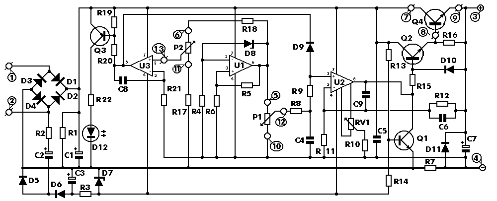
0-30 VDC Stabilized Power Supply with Current Control 0.002-3 A
The circuit begins with a step-down mains transformer featuring a secondary winding rated at 24 V/3 A, which connects across the input points at pins 1 and 2. The quality of the output supply is directly related to the transformer's...
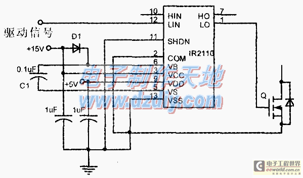
Design and making of the stabilized voltage supply of switch
Under the loading condition of the resistance, the output voltage (Uo) variable range is from 30V to 36V, with a maximum output current (Imax) of 2A. When the input voltage (U2) changes from 15V to 21V, the voltage regulation factor...
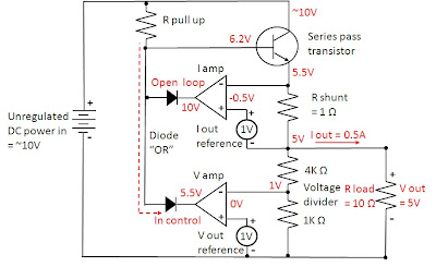
how does power supply regulate its
Most power supplies regulate either their output voltage or current at a constant level, depending on the load resistance relative to the power supply's output voltage and current settings. This can be summarized as follows: To accomplish this, most power...
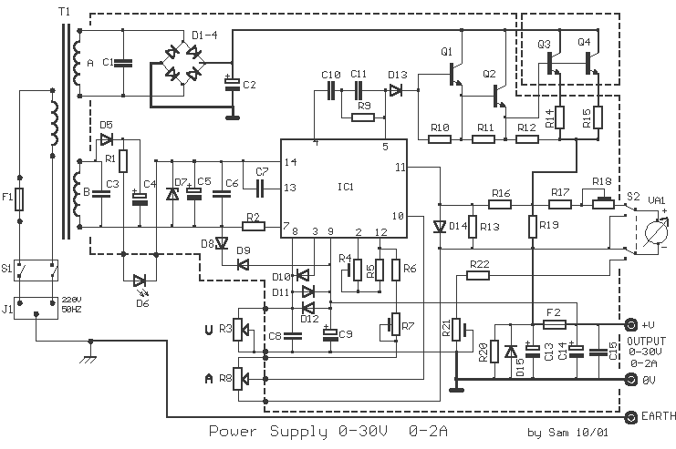
Power Supply 0-30V / 0-2A
The basic requirements for a laboratory power supply are to provide the necessary voltages and currents with low output resistance, low noise, minimal ripple, and good stabilization. These requirements are addressed within the circuit design. Many power supplies incorporate electronic...
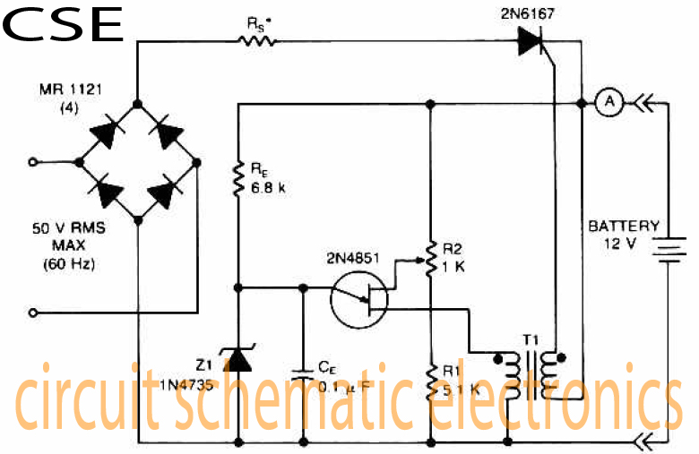
Variable charger circuit Schematic Diagram
The accumulator charger circuit must provide a voltage that matches the specifications of the batteries being charged. For a 12-volt accumulator, the output voltage should not exceed 12 volts, nor should it fall significantly below this threshold. Failure to maintain...
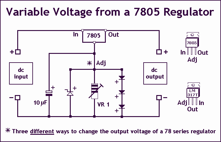
Variable Voltage Regulation
Controlling the output voltage from a regulator can be made variable in three ways:
1. Using a fixed reference zener diode to increase the output by the value of the zener
2. A variable resistor for variable output, note that...
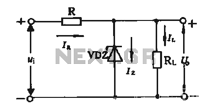
Regulator circuit silicon resistor formed
The simple voltage regulator circuit consists of a silicon regulator and a resistor. It is designed to rectify and filter DC voltage, as illustrated in the accompanying figure. The voltage regulator is connected in parallel with the load, and the...
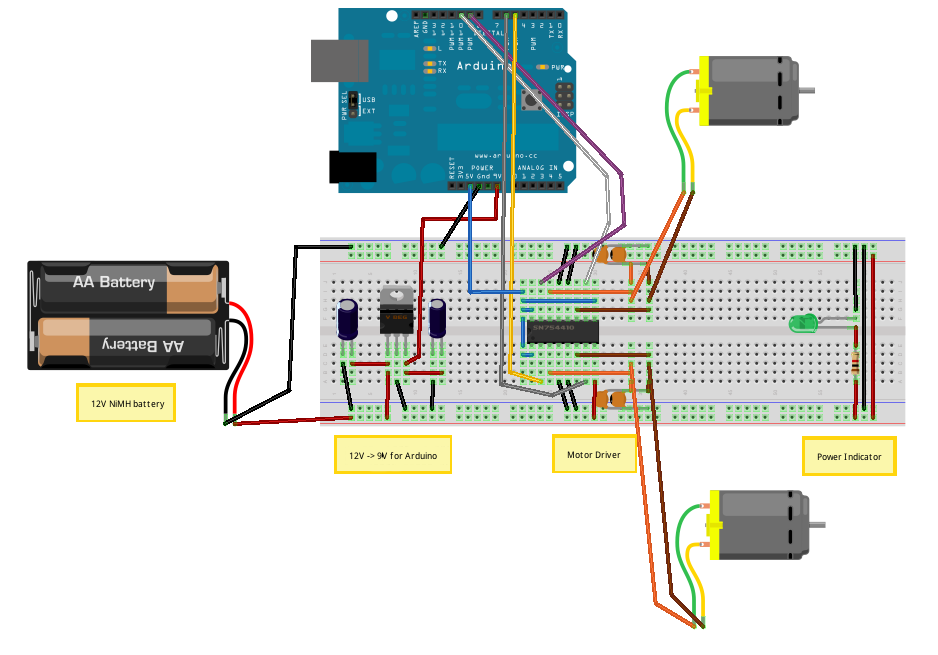
Voltage Regulators
Until Willow Garage was acquired, there was work as a Web Robotics Engineer. This title reflects a role as a full-stack engineer focused on real-time, distributed robot control. Notable projects include an XML-RPC server and client for Node.js, a deprecated...
Regulator circuit silicon resistor formed
The simple voltage regulator circuit consists of a silicon regulator and a resistor. It is designed to rectify and filter DC voltage, as illustrated in the accompanying figure. The voltage regulator is connected in parallel with the load, and the...