


DC/AC inverter
#DC/AC inverter
#multi-vibrator
#7400 IC
#transistor switching
#60 Hz frequency
#oscillator
#TR1-TR4
#current amplification
#alternating current
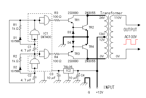
Description: The circuit utilizes an integrated circuit (IC) type multivibrator as the oscillator for alternating current, operating at approximately 60 Hz. The 7400 IC is employed for this purpose, although the 7404 IC can also be used. The oscillator signal is managed through transistors TR1 to TR4, with TR2 and TR4 serving as the main switching transistors. Due to the difficulty in driving these transistors directly from the IC, TR1 and TR3 are used to amplify the electric current. The circuit features heavy-duty wiring in the sections indicated in bold, as it handles a relatively high current of around 3 A. Some inquiries have been made regarding a 220V output. The output voltage of the inverter is determined solely by the transformer, which can be configured with a primary winding of 220V and a secondary winding of 12V. In this circuit, the primary and secondary windings are utilized in reverse, allowing for the generation of 220V AC from a 12V DC input.
The circuit operates as a basic inverter, converting DC voltage into AC voltage using a multivibrator oscillator and a transformer. The multivibrator, formed with the 7400 or 7404 IC, generates a square wave signal at a frequency of approximately 60 Hz, which is typical for household AC power in many regions. This square wave signal is fed into the bases of the transistors TR1 and TR3, which act as driver transistors. These transistors amplify the current from the IC to a level sufficient to drive the larger power transistors TR2 and TR4, which are responsible for switching the load.
The load is connected to the transformer, which is the critical component for voltage conversion. In this configuration, the transformer is designed to step up the voltage from 12V to 220V AC. The primary winding of the transformer is connected to the switching transistors, while the secondary winding provides the output voltage. It is essential to ensure that the transformer is rated for the appropriate power levels, specifically to handle the maximum current of 3 A flowing through the circuit.
The use of bold wiring in certain sections of the circuit diagram indicates that these paths must accommodate the higher current levels, requiring thicker gauge wire to prevent overheating and ensure reliability. This design consideration is crucial for maintaining the integrity of the circuit during operation.
Overall, this inverter circuit is a practical solution for converting low-voltage DC power into standard household AC voltage, suitable for powering various electrical devices. Proper attention to component ratings, especially for the transformer and transistors, is vital to ensure safe and efficient operation.It is using the IC-type multi-vibrator for the oscillator of the alternating current. The frequency is about 60 Hz. I used 7400 as the IC for the oscillator but 7404 is OK. The signal of the oscillator has the switching operation with TR1-TR4. TR2 and TR4 are the transistor for the main switching. Because these transistors are difficult to drive directly from the IC, they make amplify in the electric current using TR1 and TR3. Because the comparatively big electric current (about 3 A) flows through the part of the line that the circuit diagram is bold, the thick wiring materials are used. I was asked about 220V output from some readers. The output voltage of the inverter is decided only in the transformer. You can use the transformer with 220V as for primary(input) and 12V as for secondary(output). At my circuit, primary and secondary should be used oppositely. Then, you will be able to get AC220V from DC12V.
The circuit operates as a basic inverter, converting DC voltage into AC voltage using a multivibrator oscillator and a transformer. The multivibrator, formed with the 7400 or 7404 IC, generates a square wave signal at a frequency of approximately 60 Hz, which is typical for household AC power in many regions. This square wave signal is fed into the bases of the transistors TR1 and TR3, which act as driver transistors. These transistors amplify the current from the IC to a level sufficient to drive the larger power transistors TR2 and TR4, which are responsible for switching the load.
The load is connected to the transformer, which is the critical component for voltage conversion. In this configuration, the transformer is designed to step up the voltage from 12V to 220V AC. The primary winding of the transformer is connected to the switching transistors, while the secondary winding provides the output voltage. It is essential to ensure that the transformer is rated for the appropriate power levels, specifically to handle the maximum current of 3 A flowing through the circuit.
The use of bold wiring in certain sections of the circuit diagram indicates that these paths must accommodate the higher current levels, requiring thicker gauge wire to prevent overheating and ensure reliability. This design consideration is crucial for maintaining the integrity of the circuit during operation.
Overall, this inverter circuit is a practical solution for converting low-voltage DC power into standard household AC voltage, suitable for powering various electrical devices. Proper attention to component ratings, especially for the transformer and transistors, is vital to ensure safe and efficient operation.It is using the IC-type multi-vibrator for the oscillator of the alternating current. The frequency is about 60 Hz. I used 7400 as the IC for the oscillator but 7404 is OK. The signal of the oscillator has the switching operation with TR1-TR4. TR2 and TR4 are the transistor for the main switching. Because these transistors are difficult to drive directly from the IC, they make amplify in the electric current using TR1 and TR3. Because the comparatively big electric current (about 3 A) flows through the part of the line that the circuit diagram is bold, the thick wiring materials are used. I was asked about 220V output from some readers. The output voltage of the inverter is decided only in the transformer. You can use the transformer with 220V as for primary(input) and 12V as for secondary(output). At my circuit, primary and secondary should be used oppositely. Then, you will be able to get AC220V from DC12V.
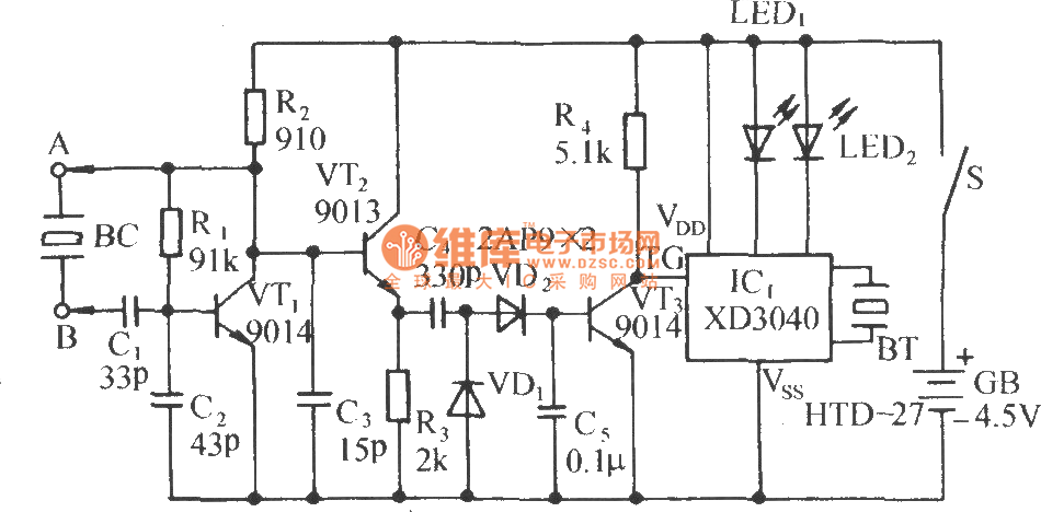
Acousto-optic detector circuit to measure the crystal
The circuit consists of a capacitance three-point oscillator, an isolation level, a voltage doubler rectifier circuit, a stereo sound circuit, and a flash display circuit. It can detect the quality of a crystal; a good crystal will emit a "Didi"...
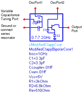
Oscillator DesignGuide Reference
The Oscillator Design Guide is integrated into Agilent EEsof's Advanced Design System environment, functioning as a smart library and interactive handbook for the creation of effective designs. It facilitates quick oscillator design, interactive component characterization, and provides in-depth insights into...
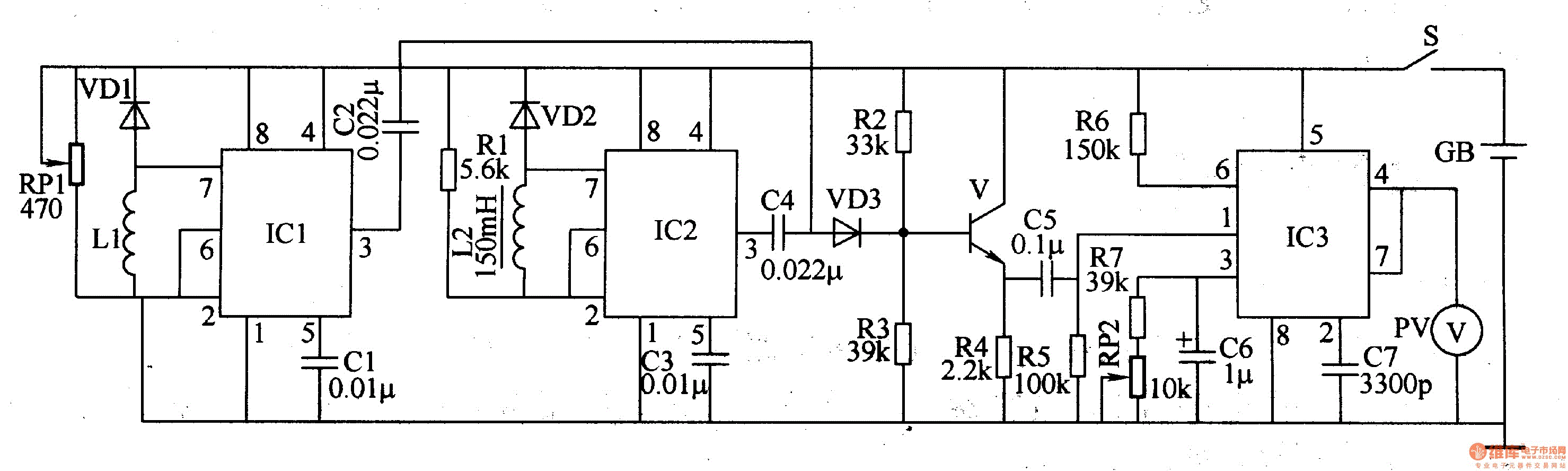
Metal detector 4
The metal detector circuit comprises a detection oscillator, a reference oscillator, a mixer, and a signal display, as illustrated in Figure 8-70. The detection oscillator circuit is made up of the time base oscillator IC1, inductor L1, potentiometer RP1, diode...
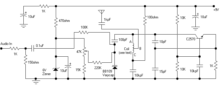
Colpitts oscillator FM transmitter
Its frequency depends on the capacitance of the vary cap diode. The center frequency is changed by varying the biasing voltage of the vary cap through the 47K pot. You can use a 75cm telescopic antenna or simply a length...
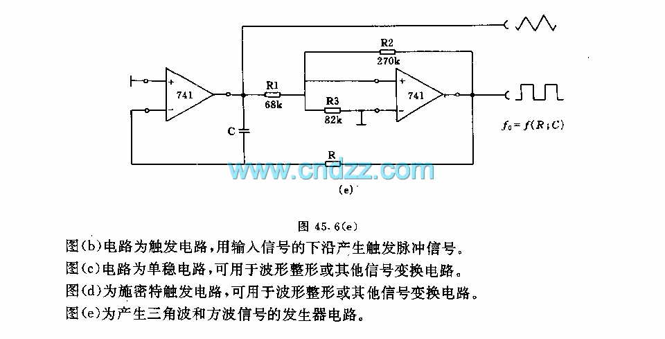
The oscillator and trigger circuit with operational amplifier
Figure a illustrates a multivibrator circuit capable of generating a square wave signal. Figure b depicts a flip-flop circuit that utilizes the falling edge of the input signal to produce a trigger pulse signal. Figure c represents a monostable circuit,...

wonky wire
The Wonky Wire circuit is based on the same oscillator used for the Flashing LED Lights. The timing components (R1/C1 and R4/C2) are significantly smaller, resulting in a higher oscillation frequency of approximately 3 kHz (3000 cycles per second). A...
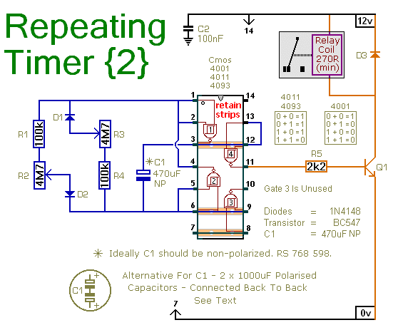
A Repeating Timer Circuit
This circuit is based on a simple asymmetric oscillator. The duration for which the relay remains energized and the duration for which it remains de-energized are independently set. With the component values indicated in the diagram, both durations are adjustable...
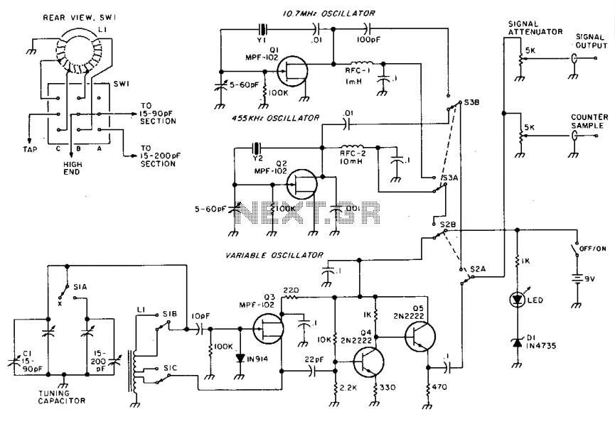
Rf-genie
A variable oscillator operates in the frequency range of 3.2 to 22 MHz across two bands, enabling coverage from 80 meters to 15 meters, in addition to accommodating most crystal filter frequencies. Optional crystal oscillators at 455 kHz and 10.7...
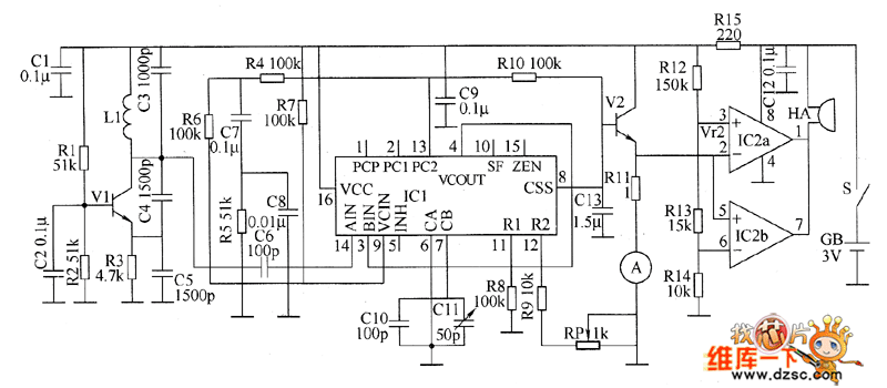
Metal detector circuit diagram 8
The metal detector circuit consists of a probe oscillator, a PLL (phase-locked loop) circuit, and an audio alarm circuit. The probe oscillator includes a detection coil (L), transistor (V1), and several resistors (R1 to R3) and capacitors (C1 to C5)....