


DC to DC Converter circuit
#DC to DC converter
#blocking oscillator
#transformer
#voltage tripler
#high voltage
#low power
#diodes
#capacitors
#power conversion
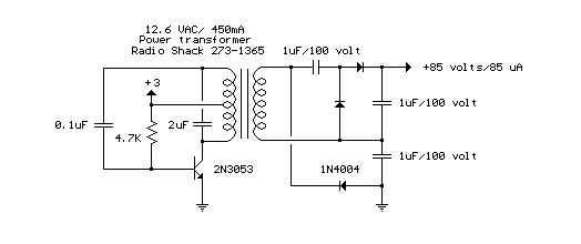
Description: The circuit is a DC to DC converter utilizing a standard 12 VAC center-tapped power transformer configured as a blocking oscillator. Although the circuit exhibits low efficiency, it generates a high voltage suitable for low-power applications. The input battery voltage is amplified by a factor across the transformer and subsequently increased by a voltage tripler composed of three capacitors and diodes connected to the high-voltage side of the transformer.
The described circuit functions as a DC to DC converter by leveraging a center-tapped transformer, which allows for the conversion of a low voltage AC input (12 VAC) into a higher voltage output suitable for various applications. The blocking oscillator configuration is essential for generating a square wave signal, which drives the transformer. This method is characterized by its simplicity and cost-effectiveness, although it comes with a trade-off in efficiency.
The operation begins with the transformer, which has a primary winding connected to the AC power source and a secondary winding that is center-tapped. This configuration provides two equal voltage outputs, which can be utilized effectively in the circuit. The blocking oscillator's feedback mechanism ensures that the transformer is driven into saturation, allowing the circuit to oscillate and produce the necessary output voltage.
Upon reaching the high-voltage side of the transformer, the voltage is further increased using a voltage tripler circuit. This tripler consists of three capacitors and diodes arranged in a specific manner to rectify and store the voltage generated. The diodes ensure that current flows in the correct direction, while the capacitors charge during the positive half-cycle of the AC waveform and discharge during the negative half-cycle, effectively multiplying the output voltage.
The end result is a high-voltage DC output that can be utilized for low-power applications, such as powering small electronic devices or charging capacitive loads. While the circuit may not be the most efficient option available, its simplicity and low component count make it a viable choice for specific scenarios where high voltage is required without the need for high power. Proper design considerations must be taken into account, including component ratings and thermal management, to ensure reliable operation within the intended application.The circuit is a DC to DC converter using a standard 12 VAC center tapped power transformer wired as a blocking oscillator. The circuit is not very efficient but will produce a high voltage usable for low power applications. The input battery voltage is raised by a factor of across the transformer and further raised by a voltage tripler consisting of three capacitors and diodes connected to the high voltage side of the transformer..
The described circuit functions as a DC to DC converter by leveraging a center-tapped transformer, which allows for the conversion of a low voltage AC input (12 VAC) into a higher voltage output suitable for various applications. The blocking oscillator configuration is essential for generating a square wave signal, which drives the transformer. This method is characterized by its simplicity and cost-effectiveness, although it comes with a trade-off in efficiency.
The operation begins with the transformer, which has a primary winding connected to the AC power source and a secondary winding that is center-tapped. This configuration provides two equal voltage outputs, which can be utilized effectively in the circuit. The blocking oscillator's feedback mechanism ensures that the transformer is driven into saturation, allowing the circuit to oscillate and produce the necessary output voltage.
Upon reaching the high-voltage side of the transformer, the voltage is further increased using a voltage tripler circuit. This tripler consists of three capacitors and diodes arranged in a specific manner to rectify and store the voltage generated. The diodes ensure that current flows in the correct direction, while the capacitors charge during the positive half-cycle of the AC waveform and discharge during the negative half-cycle, effectively multiplying the output voltage.
The end result is a high-voltage DC output that can be utilized for low-power applications, such as powering small electronic devices or charging capacitive loads. While the circuit may not be the most efficient option available, its simplicity and low component count make it a viable choice for specific scenarios where high voltage is required without the need for high power. Proper design considerations must be taken into account, including component ratings and thermal management, to ensure reliable operation within the intended application.The circuit is a DC to DC converter using a standard 12 VAC center tapped power transformer wired as a blocking oscillator. The circuit is not very efficient but will produce a high voltage usable for low power applications. The input battery voltage is raised by a factor of across the transformer and further raised by a voltage tripler consisting of three capacitors and diodes connected to the high voltage side of the transformer..
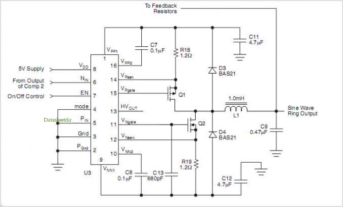
Hv440: High Voltage Ring Generator
The HV739 is a monolithic single-channel, high-speed, high-voltage ultrasound transmitter pulser. This integrated, high-performance circuit is housed in a single 5x5 mm, 32-lead QFN package. The HV739 can deliver up to ±3.0 A of source and sink current to a...
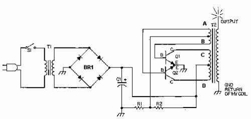
Solid State Tesla Coil/High Voltage Generator Circuit
This circuit is designed to demonstrate high-frequency high voltage, capable of producing voltages up to approximately 30 kV, depending on the transformer used. It is economical and straightforward to construct, primarily utilizing a standard TV flyback transformer. The circuit can...
Circuit Schematics
All integrated circuits (ICs) are equipped with a 0.1 µF monolithic ceramic capacitor connected across their terminals. Additionally, each board features two capacitors: a 10 µF tantalum capacitor and a 100 µF electrolytic capacitor. The START BUTTON serves as a...
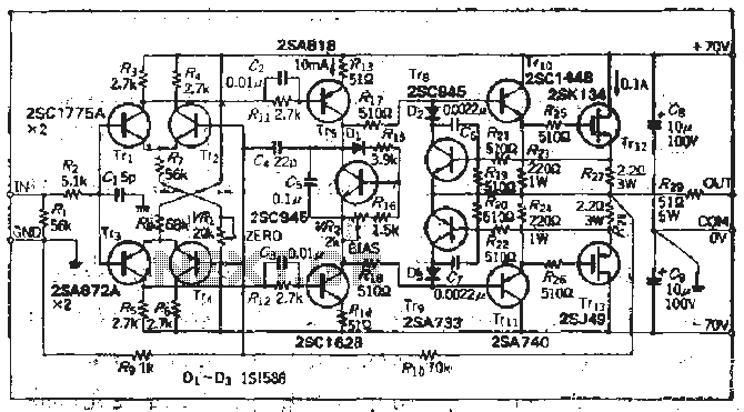
High voltage (120V), converting familiar fast (120V Shu us) power MOSFET Amplifier circuit
The south circuit consists of four parts, arranged in descending order: an NPN transistor dynamic garbage device (T1), a PNP transistor differential amplifier (T2, T3) forming a double differential circuit, two balanced output amplifiers with opposite phase, and a voltage...
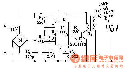
High Voltage Generator
This high voltage generator is capable of producing a stable high voltage exceeding 8kV. The circuit design is straightforward, ensuring stability and reliability. It consists of a step-down rectifier, a voltage regulator circuit, an 18kHz multivibrator-type oscillator, and a booster...
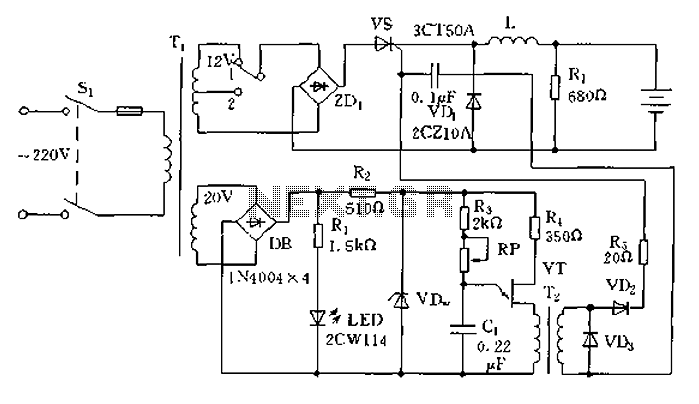
Car battery charging circuit diagram
The circuit operates on the principle of a transformer, bridge rectifier, and conditioning for battery charging. The charging current can be adjusted to approximately 12V at 100A. For battery charging, a charging rate of 10 hours requires a charging current...
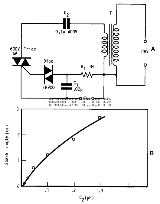
Ultra high voltage generator
By repetitively charging and discharging a capacitor through the primary winding of an induction coil with high voltage, an ultra-high electromotive force (emf) is induced in the secondary winding. Switching is performed by a triac, which is triggered by a...
High Reliability for 1200V High Voltage Integrated Circuit for Half Bridge Applications
This article presents a high reliability 1200V High Voltage Integrated Circuit (1200V HVIC) for half bridge driver applications, aimed at reducing the IC's supply current by approximately 50%.
The 1200V High Voltage Integrated Circuit (HVIC) is designed specifically for half-bridge driver...

High voltage stable power supply
The schematic diagram originates from a circuit designed for a stable power supply ranging from -100V to -1000V. For further details, refer to the page that explains the circuit diagram associated with this power supply. This stable power supply serves...