


designing grid tie inverter circuit
#grid tie inverter
#PWM
#IC 556
#high frequency generator
#pulse width modulator
#mains frequency
#TR1
#modulating frequency
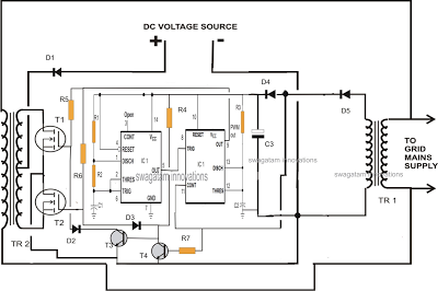
Description: A single IC 556 has been utilized to generate PWM pulses. One half of the IC is configured as a high-frequency generator, which supplies the other half of the IC, set up as a pulse width modulator. The modulating frequency is obtained from TR1, which provides precise frequency data to the IC, ensuring that the PWM signals are accurately aligned with the mains frequency.
The circuit employs the dual timer IC 556, which consists of two independent timer circuits. In this configuration, one timer operates as a high-frequency oscillator, generating a stable frequency that serves as the carrier wave for the PWM signal. This high-frequency output is essential for controlling the switching characteristics of power devices in various applications, including motor speed control, light dimming, and power regulation.
The second half of the IC 556 functions as a pulse width modulator, which modulates the width of the output pulses based on the input frequency derived from transformer TR1. The transformer is designed to step down or isolate the mains frequency, providing a reference signal that the PWM circuit can use to adjust the duty cycle of the output pulses accordingly. The precise modulation of pulse width allows for efficient control of the power delivered to the load.
The integration of TR1 ensures that the PWM output remains synchronized with the mains frequency, which is crucial for applications where timing is critical. This synchronization helps in minimizing harmonic distortion and improving the overall performance of the system. The output from the PWM circuit can be further processed or directly used to control various electronic loads, making this configuration versatile for different electronic applications.
In summary, the combination of the high-frequency generator and the pulse width modulator within the IC 556, along with the frequency reference provided by TR1, creates a robust PWM control circuit suitable for a variety of electronic applications requiring efficient power management.Here a single IC 556 has been incorporated for creating the PWM pulses. One half of the IC has been configured as the high frequency generator for feeding the other half IC which is rigged as a pulse width modulator. The sample modulating frequency is derived from TR1 which provides the exact frequency data to the IC so that the PWM are perfectly dimensioned in accordance with the mains frequency.
The circuit employs the dual timer IC 556, which consists of two independent timer circuits. In this configuration, one timer operates as a high-frequency oscillator, generating a stable frequency that serves as the carrier wave for the PWM signal. This high-frequency output is essential for controlling the switching characteristics of power devices in various applications, including motor speed control, light dimming, and power regulation.
The second half of the IC 556 functions as a pulse width modulator, which modulates the width of the output pulses based on the input frequency derived from transformer TR1. The transformer is designed to step down or isolate the mains frequency, providing a reference signal that the PWM circuit can use to adjust the duty cycle of the output pulses accordingly. The precise modulation of pulse width allows for efficient control of the power delivered to the load.
The integration of TR1 ensures that the PWM output remains synchronized with the mains frequency, which is crucial for applications where timing is critical. This synchronization helps in minimizing harmonic distortion and improving the overall performance of the system. The output from the PWM circuit can be further processed or directly used to control various electronic loads, making this configuration versatile for different electronic applications.
In summary, the combination of the high-frequency generator and the pulse width modulator within the IC 556, along with the frequency reference provided by TR1, creates a robust PWM control circuit suitable for a variety of electronic applications requiring efficient power management.Here a single IC 556 has been incorporated for creating the PWM pulses. One half of the IC has been configured as the high frequency generator for feeding the other half IC which is rigged as a pulse width modulator. The sample modulating frequency is derived from TR1 which provides the exact frequency data to the IC so that the PWM are perfectly dimensioned in accordance with the mains frequency.
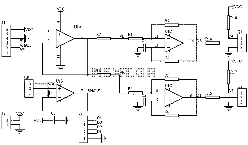
Circuit diagram of an analog circuit PWM
The image illustrates a circuit that utilizes a linear potentiometer (or linear Hall element) to control the PWM generation for two chassis drive motors in a gamepad or joystick used in model aircraft. J1 represents the handle of the potentiometer,...
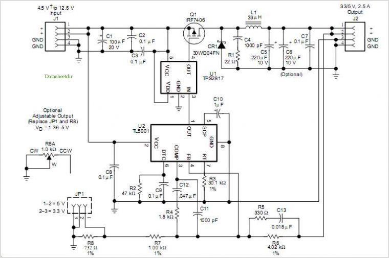
Tl5001 Pulse-width-modulation (pwm) Controller Coupled With A Tps2817 Mosfet Driver
The TLE6282G is an H-Bridge and Half Bridge Driver IC designed for high-current DC brush motor applications in PWM control mode. It is suitable for use in injector and valve applications across 12V, 24V, and 42V power networks. This IC...
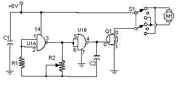
Pulse Width Modulation DC Motor Control
Often, people attempt to control DC motors with a variable resistor or variable resistor connected to a transistor. While the latter approach works well, it generates heat and hence wastes power. This simple pulse width modulation DC motor control eliminates...
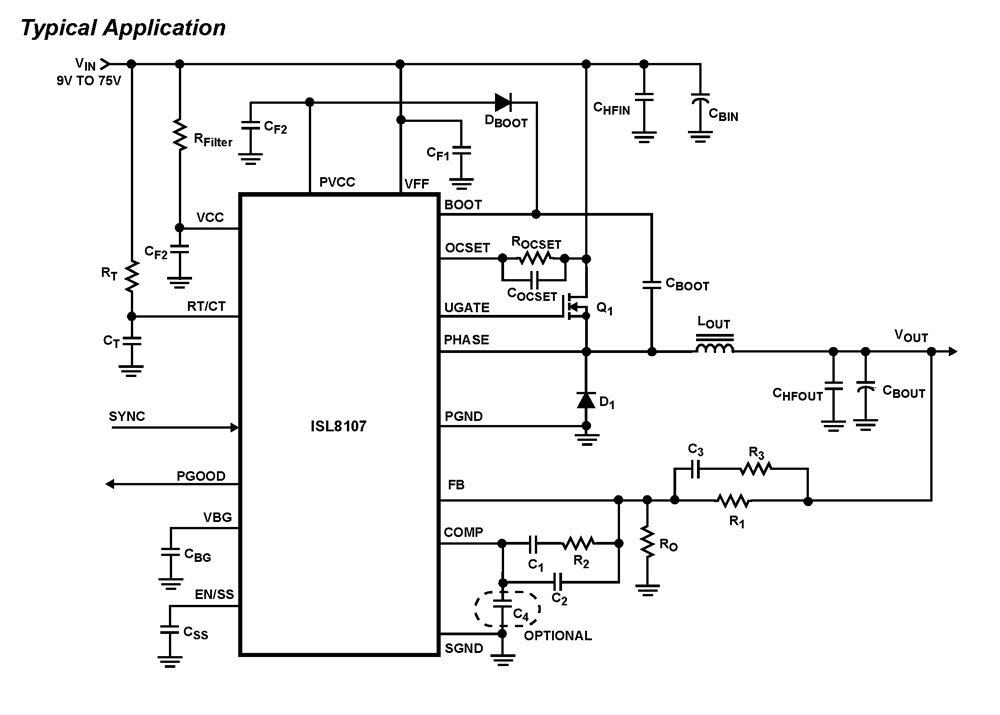
ISL8107 Single-Phase Pulse-Width Modulation (PWM) Controller with Wide (9V-75V) V
The ISL8107 is a single-phase, non-synchronous buck controller equipped with an integrated high-side MOSFET driver. It operates within an input voltage range of 9V to 75V. The internal reference voltage is 1.192V with a tolerance of ±1% across the industrial...
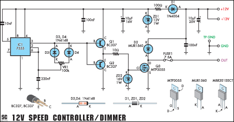
12v speed controllerdimmer
This versatile circuit functions as a speed controller for a 12V motor with a continuous rating of up to 5A or as a dimmer for a 12V halogen or standard incandescent lamp with a maximum rating of 50W. It adjusts...
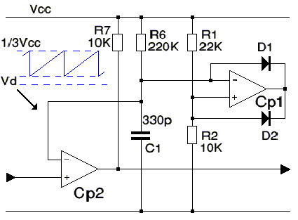
Levitation PWM
The switched controller utilized is effective; however, a pulse width modulation (PWM) circuit is more advantageous. It offers efficient operation with reduced heat generation and provides linear functioning. The implementation requires a minimal number of components. When capacitor C1 is...
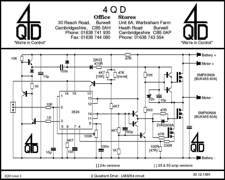
pwm 01
A commercial motor controller is more than just a circuit designed to adjust the speed of a motor. It encompasses various features that enhance its functionality, which are explained in a guided overview. To effectively control the speed of a...
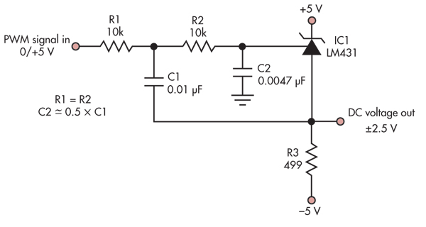
Digitally adjustable precision reference driven via PWM
This simple circuit converts a 5V PWM signal into a variable precision reference voltage with a range of -2.5V to +2.5V. Many designs, such as a digitally controlled power supply or a programmable dummy load, require a Digital to Analog...
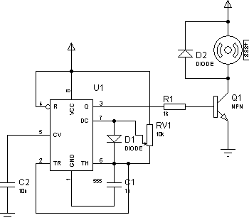
Control motor PWM schematic
There are two primary methods to control the speed of a DC motor: by varying the supply voltage and through pulse width modulation (PWM). The first method is less convenient, particularly in digital systems, as it necessitates the use of...