


Discrete Voltage Inverter
#voltage inverter
#transistors
#TTL clock
#negative voltage
#discrete components
#n-p-n transistors
#capacitor
#power supply
#circuit design
#electronics
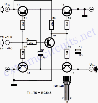
Description: The circuit illustrated in the diagram allows for the generation of a negative voltage without utilizing integrated circuits. It employs five n-p-n transistors controlled by a TTL clock operating at approximately 1 kHz. When the clock signal is high, transistors T1 and T2 connect capacitor C1 to the supply voltage, UIN, which is typically 5 V. During this phase, transistor T5 is in conduction, keeping transistors T3 and T4 in the off state. When the clock signal goes low, T5 is turned off, causing transistors T3 and T4 to activate through pull-up resistor R6 and either R4 or R5. This action results in the charge on C1 being shared between C1 and C2. Given that the positive terminal of C2 is at ground potential, its negative terminal must become negative with respect to earth. The high level of the clock input must be comparable to the positive input voltage, UIN, to ensure that T1 can be activated. The clock frequency is set to around 1 kHz to maintain a duty cycle ratio of 1:1. Modifying this ratio will yield a different level of negative output voltage, which will always be less than that achieved with a 1:1 ratio.
The circuit operates as a negative voltage generator utilizing a charge pump configuration. The key components include five n-p-n transistors (T1, T2, T3, T4, and T5), two capacitors (C1 and C2), and several resistors (R4, R5, and R6). The transistors function as switches, controlled by a TTL clock signal.
When the clock signal is high, T1 and T2 are turned on, allowing C1 to charge to the supply voltage (UIN). The voltage across C1 is then utilized to influence the operation of T3 and T4. During this time, T5 remains on, ensuring that T3 and T4 do not conduct.
Once the clock signal transitions to low, T5 is deactivated, leading to the activation of T3 and T4 through the pull-up resistor. This change allows the stored charge in C1 to be transferred to C2, effectively inverting the voltage at the negative terminal of C2 relative to ground. This mechanism creates a negative voltage output, which can be utilized in various applications requiring a negative supply.
The design's reliance on discrete components rather than integrated circuits offers simplicity and ease of implementation, particularly in low-power applications. The duty cycle of the clock signal is crucial; a 1:1 ratio ensures optimal performance and stability of the output voltage. Adjustments to the duty cycle can fine-tune the output voltage level, although the negative voltage generated will always be less than that produced under a 1:1 duty cycle condition.
This circuit can be applied in scenarios where a negative voltage is necessary, such as in operational amplifier configurations or biasing for certain transistor circuits. Overall, this design exemplifies an efficient method for generating a negative supply voltage using basic electronic components.The circuit in the diagram enables a negative voltage to be derived without the use of integrated circuits. Instead, it uses five n-p-n transistors that are driven by a 1 kHz (approx) TTL clock. When the clock input is high, transistors T1 and T2 link capacitor C1 to the supply voltage, UIN, which typically is 5 V.
During this process, transistor T5 conducts so that T3 and T4 are off. When the clock input is low, T5 is cut off, whereupon transistors T3 and T4 are switched on via pull-up resistor R6 and either R4 or R5. This results in the charge on C1 being shared between this capacitor and C2 Since the +ve terminal of C2 is at ground potential, its ve terminal must become negative w.
r. t. earth. The high level at the clock input must be of the same order as the positive input voltage, UIN, otherwise T1 cannot be switched on. The clock frequency should be around 1 kHz to ensure a duty cycle ratio of 1:1. Altering the ratio results in a different level of negative output voltage, but this is always smaller than that with a ratio of 1:1.
The circuit operates as a negative voltage generator utilizing a charge pump configuration. The key components include five n-p-n transistors (T1, T2, T3, T4, and T5), two capacitors (C1 and C2), and several resistors (R4, R5, and R6). The transistors function as switches, controlled by a TTL clock signal.
When the clock signal is high, T1 and T2 are turned on, allowing C1 to charge to the supply voltage (UIN). The voltage across C1 is then utilized to influence the operation of T3 and T4. During this time, T5 remains on, ensuring that T3 and T4 do not conduct.
Once the clock signal transitions to low, T5 is deactivated, leading to the activation of T3 and T4 through the pull-up resistor. This change allows the stored charge in C1 to be transferred to C2, effectively inverting the voltage at the negative terminal of C2 relative to ground. This mechanism creates a negative voltage output, which can be utilized in various applications requiring a negative supply.
The design's reliance on discrete components rather than integrated circuits offers simplicity and ease of implementation, particularly in low-power applications. The duty cycle of the clock signal is crucial; a 1:1 ratio ensures optimal performance and stability of the output voltage. Adjustments to the duty cycle can fine-tune the output voltage level, although the negative voltage generated will always be less than that produced under a 1:1 duty cycle condition.
This circuit can be applied in scenarios where a negative voltage is necessary, such as in operational amplifier configurations or biasing for certain transistor circuits. Overall, this design exemplifies an efficient method for generating a negative supply voltage using basic electronic components.The circuit in the diagram enables a negative voltage to be derived without the use of integrated circuits. Instead, it uses five n-p-n transistors that are driven by a 1 kHz (approx) TTL clock. When the clock input is high, transistors T1 and T2 link capacitor C1 to the supply voltage, UIN, which typically is 5 V.
During this process, transistor T5 conducts so that T3 and T4 are off. When the clock input is low, T5 is cut off, whereupon transistors T3 and T4 are switched on via pull-up resistor R6 and either R4 or R5. This results in the charge on C1 being shared between this capacitor and C2 Since the +ve terminal of C2 is at ground potential, its ve terminal must become negative w.
r. t. earth. The high level at the clock input must be of the same order as the positive input voltage, UIN, otherwise T1 cannot be switched on. The clock frequency should be around 1 kHz to ensure a duty cycle ratio of 1:1. Altering the ratio results in a different level of negative output voltage, but this is always smaller than that with a ratio of 1:1.
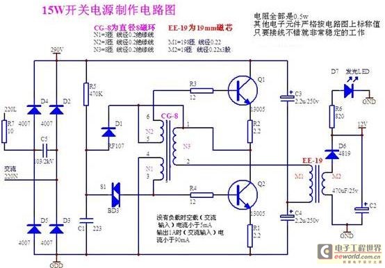
Structural analysis of switching power supply
A daily switching power supply primarily provides direct current (DC) power to electronic devices. The required DC voltage for electronic devices typically ranges from several volts to over ten volts, while the input voltage from the mains supply is either...
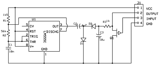
A voltage inverter circuit
Our programmable MP3 player has an interface to an LCD with a HD44780 controller. These are alphanumeric LCDs with one to 4 lines of text and 16 to 40 characters per line. However, these LCDs (and LCDs in general) exist...
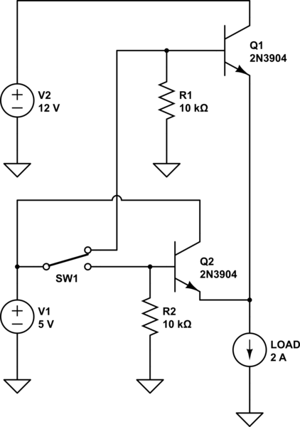
power How can I switch a high current with a low-rated switch
The project involves designing and constructing a breadboard power supply that draws power from an ATX-like switch-mode power supply (SMPS) using a 4-pin Molex connector. The design features a switch to select either a 12V or 5V output. However, the...
own capacitor
The capacitor is composed of two sheets of aluminum foil. It is essential to keep the foil within the plastic packets and connect them using crocodile clips, ensuring that the clips do not touch each other. The initial frequency of...
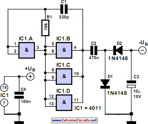
Negative Auxiliary Voltage
Some circuits require a negative supply voltage that only needs to deliver a small current. Providing a separate transformer winding for this purpose, potentially with a rectifier and filter capacitor, would be an extravagant solution. An alternative approach involves utilizing...
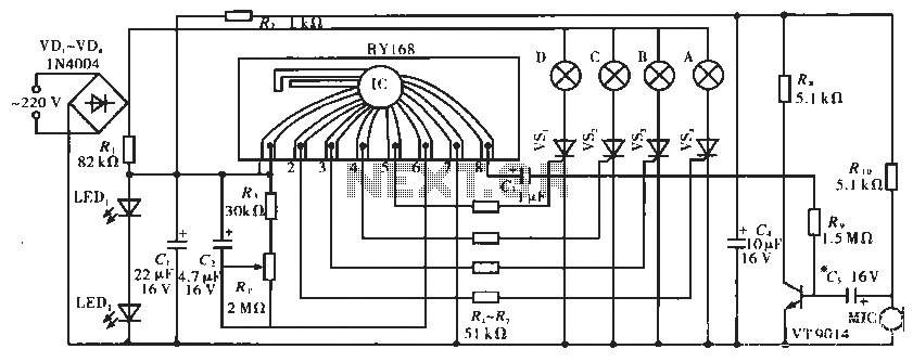
Lighting controller circuit
The circuit operates with a controller that includes a power supply circuit, a control circuit, and an audio amplifier, which are three distinct components. The power circuit comprises diodes VD1 to VD4, resistor R1, capacitor C1, LED1, LED2, and additional...
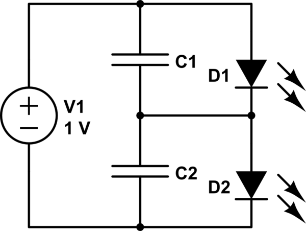
Charging a low-voltage high-C capacitor. Efficiently
The first option is a Zener diode. There are several 2.2V Zener diodes available that could adequately protect the capacitor. However, a significant drawback is that half the energy may be wasted across the diode short. The question arises whether...
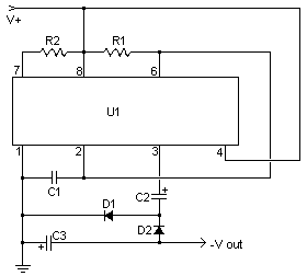
Voltage Inverter
This simple circuit is a good solution to the powering a dual supply op amp from a single battery problem. The circuit simply takes a positive voltage and inverts it. It uses only one 555 timer and a few other...

symmetric 12v to 5v converter
Symmetric 12V to 5V converter power supply. Refer to the designated page for an explanation regarding the associated circuit diagram.
The symmetric 12V to 5V converter power supply is designed to efficiently step down a 12V input voltage to a regulated...