


IC Controlled Emergency Light With Charger Circuit
#emergency light
#battery charger
#inverter
#over-charge protection
#relay
#12V to 220V
#automatic switching
#IC controlled
#mains failure
#LED
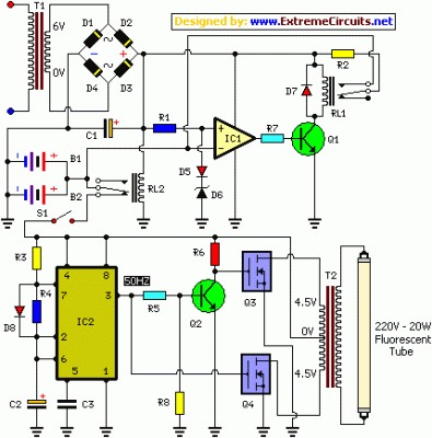
Description: The circuit diagram presented illustrates an IC-controlled emergency light with a charger, functioning as a 12V to 220V AC inverter circuit. This emergency light circuit is designed to automatically activate in the event of a mains failure, while also incorporating a battery charger equipped with over-charge protection. In the absence of mains power, relay RL2 remains in a de-energized state, allowing battery supply to be directed to the inverter section through its normally closed (N/C) contacts and switch S1.
The IC-controlled emergency light circuit operates on a dual functionality principle, serving both as an emergency lighting solution and a battery charging system. The core components include an inverter circuit that converts the 12V DC battery voltage to 220V AC output, suitable for powering standard household appliances during power outages.
The operation begins with the detection of a mains failure. When the mains voltage drops below a certain threshold, the relay RL2 is triggered to switch to its de-energized state. This action connects the battery to the inverter circuit, enabling the inverter to generate 220V AC output. The inverter typically consists of a transformer and a switching mechanism, often using transistors or MOSFETs, to efficiently convert the DC voltage to AC.
Simultaneously, the circuit includes a battery charging mechanism that ensures the battery remains charged when mains power is available. The charger is designed with over-charge protection to prevent damage to the battery. This is typically achieved through a voltage regulation circuit that monitors the battery voltage and disconnects the charging current when the battery reaches its full charge capacity.
Switch S1 plays a critical role in the circuit by allowing manual intervention to enable or disable the inverter operation, providing flexibility in usage. Overall, this circuit design combines safety, efficiency, and reliability, making it an effective solution for emergency lighting needs.Here is the circuit diagram of IC Controlled Emergancy Light With Charger or simply 12V to 220V AC inverter circuit. The circuit shown here is that of the IC controlled emergency light. Its main features are: automatic switching-on of the light on mains failure and battery charger with over-charge protection.
When mains is absent, relay RL2 is in de-energized state, feeding battery supply to inverter section via its N/C contacts and switch S1
The IC-controlled emergency light circuit operates on a dual functionality principle, serving both as an emergency lighting solution and a battery charging system. The core components include an inverter circuit that converts the 12V DC battery voltage to 220V AC output, suitable for powering standard household appliances during power outages.
The operation begins with the detection of a mains failure. When the mains voltage drops below a certain threshold, the relay RL2 is triggered to switch to its de-energized state. This action connects the battery to the inverter circuit, enabling the inverter to generate 220V AC output. The inverter typically consists of a transformer and a switching mechanism, often using transistors or MOSFETs, to efficiently convert the DC voltage to AC.
Simultaneously, the circuit includes a battery charging mechanism that ensures the battery remains charged when mains power is available. The charger is designed with over-charge protection to prevent damage to the battery. This is typically achieved through a voltage regulation circuit that monitors the battery voltage and disconnects the charging current when the battery reaches its full charge capacity.
Switch S1 plays a critical role in the circuit by allowing manual intervention to enable or disable the inverter operation, providing flexibility in usage. Overall, this circuit design combines safety, efficiency, and reliability, making it an effective solution for emergency lighting needs.Here is the circuit diagram of IC Controlled Emergancy Light With Charger or simply 12V to 220V AC inverter circuit. The circuit shown here is that of the IC controlled emergency light. Its main features are: automatic switching-on of the light on mains failure and battery charger with over-charge protection.
When mains is absent, relay RL2 is in de-energized state, feeding battery supply to inverter section via its N/C contacts and switch S1

Running Message Display
Light-emitting diodes (LEDs) are advantageous due to their compact size, low current consumption, and vibrant colors. This circuit features a running message display where the letters formed by an LED arrangement illuminate progressively. Once all letters of the message are...
Interactive Toy Traffic Lights
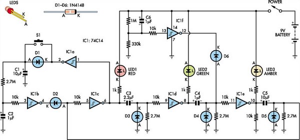
This toy traffic signal utilizes a single, cost-effective hex Schmitt-trigger inverter IC (IC1a-IC1f) to directly control three colored LEDs (red, green, and amber). Upon activation, the circuit illuminates the red signal for 30 seconds, followed by the green signal for...
Multipattern Running LEDs
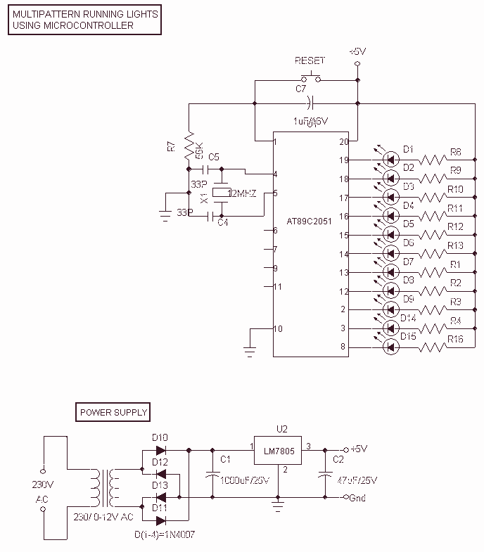
This Project Multi-Pattern Running light is used to generate several designs of Running Lights. We use ten LEDs for display. The designs can be selected by using two switches UP and DOWN. The 8 bit Microcontroller is used to control...
Using AC for LED Christmas Lights
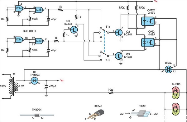
This circuit utilizes low-voltage AC to power a string of approximately 50 bi-color LEDs, with two LEDs connected in inverse parallel. The power supplied to the LEDs is managed by a Triac and two optocouplers, whose phototransistors are also connected...
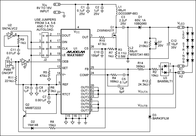
Display Backlighting Using High-Brightness LEDs and SEPIC Power Modules
This application note discusses the use of SEPIC power modules to supply the necessary power for driving high-brightness LED arrays. These arrays serve as display backlights and necessitate a wide dimming range. The SEPIC configuration offers an efficient and adaptable...
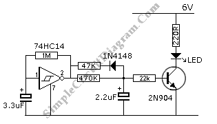
Blinking LED Emulates Incandescent Bulb
This circuit features a flashing LED that emulates the behavior of an incandescent lamp. The characteristic of an incandescent lamp is that it cannot abruptly change its brightness.
The flashing LED circuit designed to mimic an incandescent lamp operates by simulating...
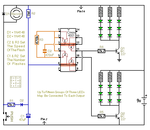
Three Flashing LED Doorbells For The Hearing Impaired
When the push switch is activated, the buzzer sounds, and the LEDs start to flash. For the hearing members of the household, the buzzer functions as a standard doorbell, providing reassurance to the visitor that the doorbell is operational. Upon...
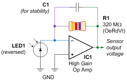
Color Sensor from a Reversed LED and Op Amp
One of the first lessons that electronics students learn is that an LED emits light when current flows through it. However, it is also true that when an LED is connected in reverse, it can generate a current flow when...
4 time ON-OFF relay circuit
A circuit is required where, upon power application, a timer triggers, keeping a relay in the off state. Once the timer completes its cycle, the relay will activate.
The circuit design consists of a timer integrated with a relay to control...