


modifying 4047 ic inverter into sine
#IC 4047
#PWM
#sine wave inverter
#square wave inverter
#modified sine wave
#power electronics
#inverter design
#AC/DC conversion
#circuit modification
#Nigeria
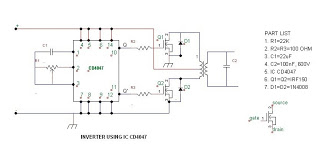
Description: The post discusses how to modify an ordinary square wave inverter using IC 4047 into a modified sine wave inverter through PWM technology. The idea was requested by Mr. Philip, a resident of Nigeria, who has been an avid follower of the blog and its electronic designs, particularly the inverter designs. He seeks advice on a PWM-controlled modified sine wave inverter he is designing. This design is tentative, and he has not yet implemented it but would like feedback and answers to some questions he has been unable to resolve. In the diagram, the IC CD4047 generates square wave pulses at 50Hz, which are used to alternately switch on MOSFETs Q1 and Q2. The PWM circuit is based on IC NE555, and its output is applied to the gate of Q3 to provide the PWM. Additionally, he has two questions: first, can square waves be used for PWM pulses? Second, what is the relationship between PWM frequency and supply frequency, and what PWM frequency should be used for a 50Hz inverter output? The configuration shown in the second figure would work, but adding one more MOSFET would unnecessarily increase cost and heat dissipation, making the circuit slightly inefficient. The PWM transforms the flat square waves into a modified square wave by chopping them into smaller calculated sections, ensuring that the overall RMS of the waveform closely resembles an actual sine wave while maintaining the peak level equal to the original square wave input.
The proposed circuit design aims to convert a basic square wave inverter into a modified sine wave inverter using pulse-width modulation (PWM) techniques. The central component, the CD4047 integrated circuit, serves as an oscillator to generate square wave signals at a frequency of 50Hz. These square wave outputs are pivotal for driving the switching elements of the inverter, specifically the MOSFETs Q1 and Q2, which alternate in conduction to create the AC output.
The PWM control is implemented using the NE555 timer IC, which is configured in astable mode to produce a variable duty cycle output. This output is fed to the gate of a third MOSFET, Q3, which modulates the pulse width of the square wave, effectively transforming it into a modified sine wave. The PWM technique allows for the adjustment of the effective voltage and the shape of the waveform, enhancing the inverter's efficiency and output quality.
Regarding the questions posed, the use of square waves for PWM pulses is generally not advisable, as PWM relies on varying the duty cycle to create an effective output that simulates a sine wave. The relationship between PWM frequency and supply frequency is crucial; the PWM frequency should be significantly higher than the supply frequency to ensure smooth waveform generation. A common practice is to set the PWM frequency to at least 10 times the supply frequency, suggesting a PWM frequency of around 500Hz for a 50Hz output.
The configuration's efficiency is a consideration; while adding additional MOSFETs may provide redundancy or improved performance, it also introduces increased costs and thermal management challenges. The design must balance performance and efficiency, ensuring that the modified sine wave output closely approximates a true sine wave while optimizing component usage and minimizing heat generation.The post discuses how to modify an ordinary square wave inverter using IC 4047 into a modified sine wave inverter through PWM technology. The idea was requested by Mr. Philip I am a Nigerian living in Nigeria and I have been an avid follower of your blog and your electronic designs especially your inverter designs.
I hope that i am not going t o be a bother, but I need some advice with a PWM-controlled modified sine wave inverter I am designing so I want to seek your expert opinion. This design is tentative, I haven`t implemented it yet but I would like you to take a look at it and tell me what you think.
Also I want you to help answer some questions which I have not been able to find answers to. In the diagram, the IC CD4047 is responsible for generating square wave pulses at 50Hz which will be used to alternately switch on MOSFETS Q1 and Q2. The PWM circuit will be based on IC NE555 and its output will be applied to the gate of Q3 so that Q3 will provide the PWM.
Besides this, I have two questions. First, can I use square waves for the PWM pulses Second, what is the relationship between PWM frequency and supply frequency What PWM frequency should I use for a 50Hz inverter output The configuration shown in the second figure would work but the addition of one more mosfet would unnecessarily increase cost and heat dissipation making the circuit sightly inefficient. The PWM transforms the flat square waves into a modified square wave by chopping them into smaller calculated sections such that the overall RMS of the waveform becomes as close as possible to an actual sine counterpart, yet maintaining the peak level equal to the actual square wave input.
The concept may be learned in details here:
The proposed circuit design aims to convert a basic square wave inverter into a modified sine wave inverter using pulse-width modulation (PWM) techniques. The central component, the CD4047 integrated circuit, serves as an oscillator to generate square wave signals at a frequency of 50Hz. These square wave outputs are pivotal for driving the switching elements of the inverter, specifically the MOSFETs Q1 and Q2, which alternate in conduction to create the AC output.
The PWM control is implemented using the NE555 timer IC, which is configured in astable mode to produce a variable duty cycle output. This output is fed to the gate of a third MOSFET, Q3, which modulates the pulse width of the square wave, effectively transforming it into a modified sine wave. The PWM technique allows for the adjustment of the effective voltage and the shape of the waveform, enhancing the inverter's efficiency and output quality.
Regarding the questions posed, the use of square waves for PWM pulses is generally not advisable, as PWM relies on varying the duty cycle to create an effective output that simulates a sine wave. The relationship between PWM frequency and supply frequency is crucial; the PWM frequency should be significantly higher than the supply frequency to ensure smooth waveform generation. A common practice is to set the PWM frequency to at least 10 times the supply frequency, suggesting a PWM frequency of around 500Hz for a 50Hz output.
The configuration's efficiency is a consideration; while adding additional MOSFETs may provide redundancy or improved performance, it also introduces increased costs and thermal management challenges. The design must balance performance and efficiency, ensuring that the modified sine wave output closely approximates a true sine wave while optimizing component usage and minimizing heat generation.The post discuses how to modify an ordinary square wave inverter using IC 4047 into a modified sine wave inverter through PWM technology. The idea was requested by Mr. Philip I am a Nigerian living in Nigeria and I have been an avid follower of your blog and your electronic designs especially your inverter designs.
I hope that i am not going t o be a bother, but I need some advice with a PWM-controlled modified sine wave inverter I am designing so I want to seek your expert opinion. This design is tentative, I haven`t implemented it yet but I would like you to take a look at it and tell me what you think.
Also I want you to help answer some questions which I have not been able to find answers to. In the diagram, the IC CD4047 is responsible for generating square wave pulses at 50Hz which will be used to alternately switch on MOSFETS Q1 and Q2. The PWM circuit will be based on IC NE555 and its output will be applied to the gate of Q3 so that Q3 will provide the PWM.
Besides this, I have two questions. First, can I use square waves for the PWM pulses Second, what is the relationship between PWM frequency and supply frequency What PWM frequency should I use for a 50Hz inverter output The configuration shown in the second figure would work but the addition of one more mosfet would unnecessarily increase cost and heat dissipation making the circuit sightly inefficient. The PWM transforms the flat square waves into a modified square wave by chopping them into smaller calculated sections such that the overall RMS of the waveform becomes as close as possible to an actual sine counterpart, yet maintaining the peak level equal to the actual square wave input.
The concept may be learned in details here:
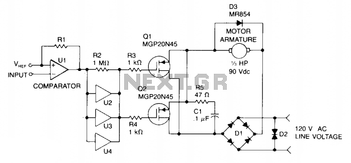
Pwm motor speed control
Speed control is achieved through pulse width modulation (PWM) of the gates of two MGP20N45 TMOS devices. Consequently, the motor speed is directly proportional to the pulse width of the incoming digital signal, which can be generated by a microprocessor...
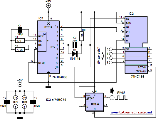
Discrete PWM Generator Circuit
PWM waveforms are frequently employed to regulate the speed of DC motors. The mark/space ratio of the digital waveform can be established either by utilizing an adjustable analog voltage level (as seen in a NE555-based PWM generator) or through digital...
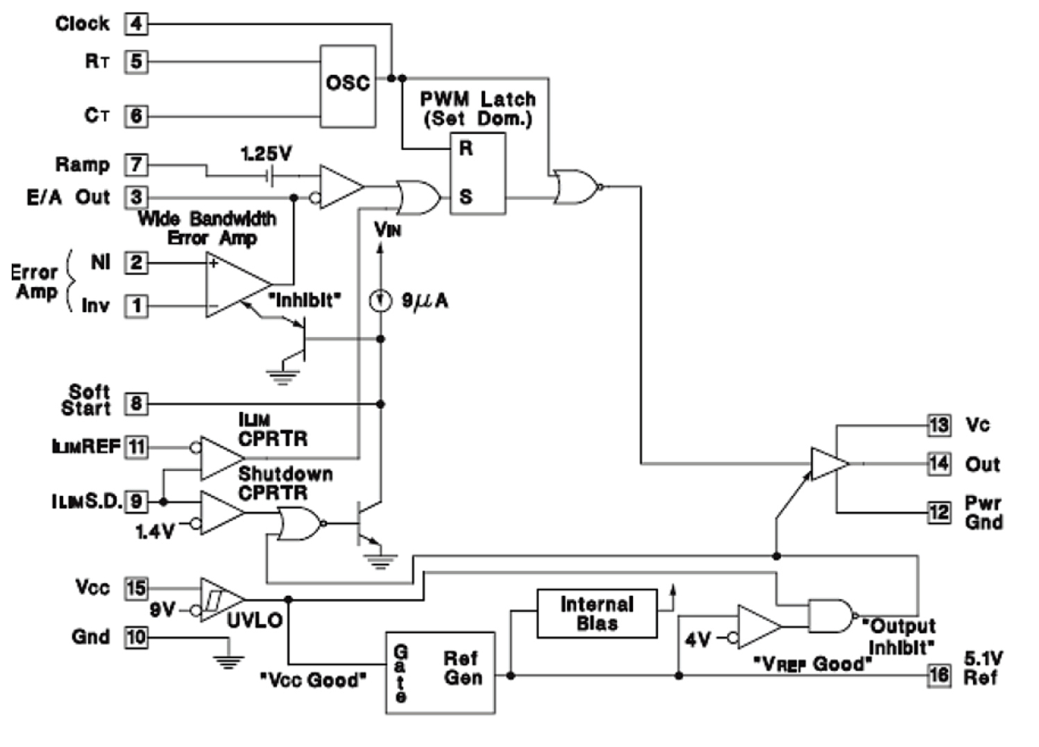
Keep The Ramp right
If the ramp driving your PWM-based controller is not linear, monotonic, or is simply noisy, your DC/DC converter will not perform optimally. It is essential to understand how to achieve the best performance from your system. A typical DC/DC power...
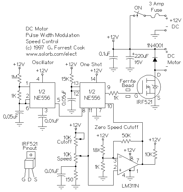
PWM DC Motor Speed Control
This is a circuit for controlling the speed of small DC motors; it works nicely as a speed controller for an HO or N gauge model railroad. More: The left half of the 556 dual timer IC is used as...
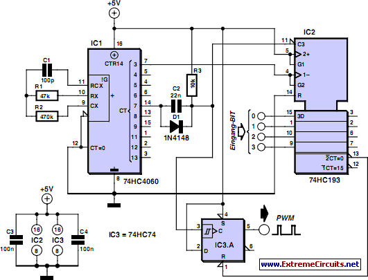
Discrete PWM Generator Circuit
PWM waveforms are widely utilized to regulate the speed of DC motors. The duty cycle of the digital waveform can be established either through an adjustable analog voltage level (as seen in a NE555-based PWM generator) or through digital binary...
PWM DC Motor Speed Control
This is a circuit for controlling the speed of small DC motors; it works nicely as a speed controller for an HO or N gauge model railroad. More: The left half of the 556 dual timer IC is used as...
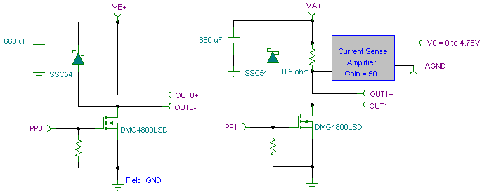
Pulse Width Modulation PWM Controller Board for DC Loads/devices
The PWM pulse width modulation controller board enables 9S12/HCS12 microcontrollers or PIC microcontrollers to output 8 channels, each capable of delivering 5 DC amps, while incorporating current sensing for the PWM waveform. This PWM driver circuit is suitable for applications...
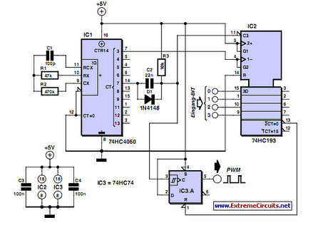
Discrete PWM Generator Circuit
PWM waveforms are frequently utilized to regulate the speed of DC motors. The duty cycle of the digital waveform can be defined using an adjustable parameter.
PWM (Pulse Width Modulation) is a technique employed to control the power delivered to electrical...

Pulse Width Modulation DC Motor Controls
This simple pulse width modulation (PWM) DC motor control addresses common issues by regulating motor speed through the application of short pulses. The duration of these pulses is varied to adjust the motor speed; longer pulses result in faster motor...