


PIC controlled 500W Modified Sine Wave Inverter
#PIC16F628A
#modified sine wave
#500W
#microcontroller
#AC/DC
#power inverter
#PIC controlled
#switching
#energy conversion
#power electronics
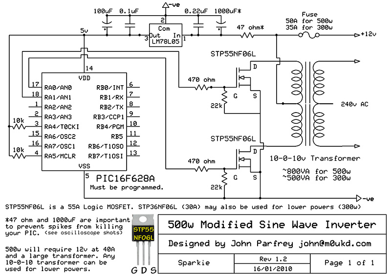
Description: PIC controlled 500W Modified Sine Wave Inverter. The PIC16F628A is programmed to produce a logic 5V signal for 5ms at pin 17, followed by 15ms off.
The described circuit implements a 500W modified sine wave inverter controlled by a PIC16F628A microcontroller. The primary function of the inverter is to convert DC voltage into a modified AC output suitable for powering various devices. The PIC16F628A microcontroller is programmed to generate a control signal at pin 17, which operates at a logic level of 5V. This signal is activated for a duration of 5 milliseconds, followed by a 15-millisecond off period, creating a pulsed output that is essential for the modulation of the inverter's output waveform.
The inverter circuit typically includes several key components: a DC power source (such as a battery), a power stage that may consist of MOSFETs or IGBTs to switch the DC input, and a transformer to step up the voltage to the desired AC level. The output waveform is modified to approximate a sine wave, which is more suitable for powering inductive loads compared to a pure square wave.
In addition to the microcontroller, the circuit may incorporate feedback mechanisms to monitor output voltage and current, ensuring stable operation and protection against overload conditions. The use of appropriate filtering components, such as capacitors and inductors, is critical to smooth the output waveform and reduce harmonic distortion.
Overall, the design emphasizes efficiency and reliability, making it suitable for various applications, including powering household appliances, tools, and other electronic devices that require a modified sine wave input.PIC controlled 500W `Modified Sine Wave` Inverter. The PIC16F628A is programmed to produce a logic 5v signal for 5ms at pin 17 then 15ms off..
The described circuit implements a 500W modified sine wave inverter controlled by a PIC16F628A microcontroller. The primary function of the inverter is to convert DC voltage into a modified AC output suitable for powering various devices. The PIC16F628A microcontroller is programmed to generate a control signal at pin 17, which operates at a logic level of 5V. This signal is activated for a duration of 5 milliseconds, followed by a 15-millisecond off period, creating a pulsed output that is essential for the modulation of the inverter's output waveform.
The inverter circuit typically includes several key components: a DC power source (such as a battery), a power stage that may consist of MOSFETs or IGBTs to switch the DC input, and a transformer to step up the voltage to the desired AC level. The output waveform is modified to approximate a sine wave, which is more suitable for powering inductive loads compared to a pure square wave.
In addition to the microcontroller, the circuit may incorporate feedback mechanisms to monitor output voltage and current, ensuring stable operation and protection against overload conditions. The use of appropriate filtering components, such as capacitors and inductors, is critical to smooth the output waveform and reduce harmonic distortion.
Overall, the design emphasizes efficiency and reliability, making it suitable for various applications, including powering household appliances, tools, and other electronic devices that require a modified sine wave input.PIC controlled 500W `Modified Sine Wave` Inverter. The PIC16F628A is programmed to produce a logic 5v signal for 5ms at pin 17 then 15ms off..
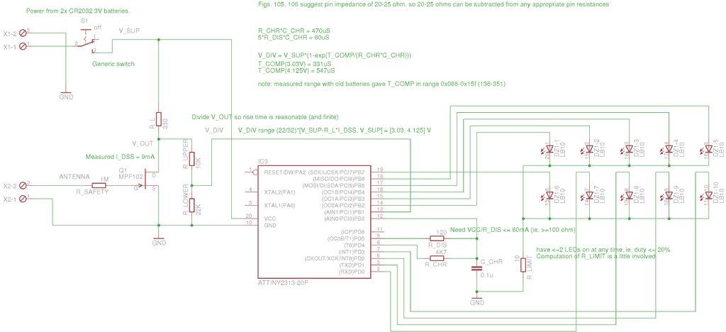
Microcontroller interface electrometer
A method for measuring static electricity for a science project was sought. An old copy of "Getting Started in Electronics" by Forrest M. Mims III was referenced for guidance.
To create a static electricity measurement circuit, a simple design can be...
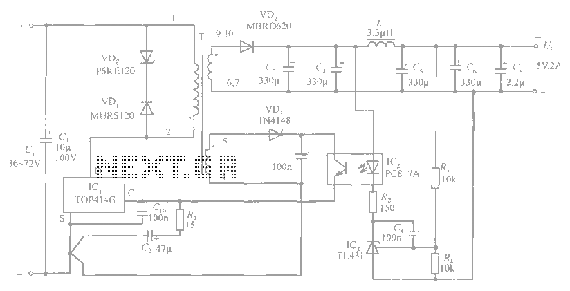
5V / 2A isolated switching power supply circuit diagram
The circuit diagram includes an input filter capacitor C1 and a primary clamp composed of VDz and VD1. The resistor R1 is connected to the control terminal. C2 serves as a bypass capacitor. The TOP414GC-S is connected in parallel to...
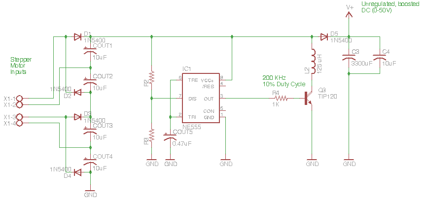
Switching Power Supply
The circuit depicted in the schematic below represents an enhanced generator electronics system. It is an unregulated switcher designed to maximize sound output while ensuring prolonged CPU operation. This circuit efficiently transfers electrical energy from the generator, outperforming traditional rectifier...
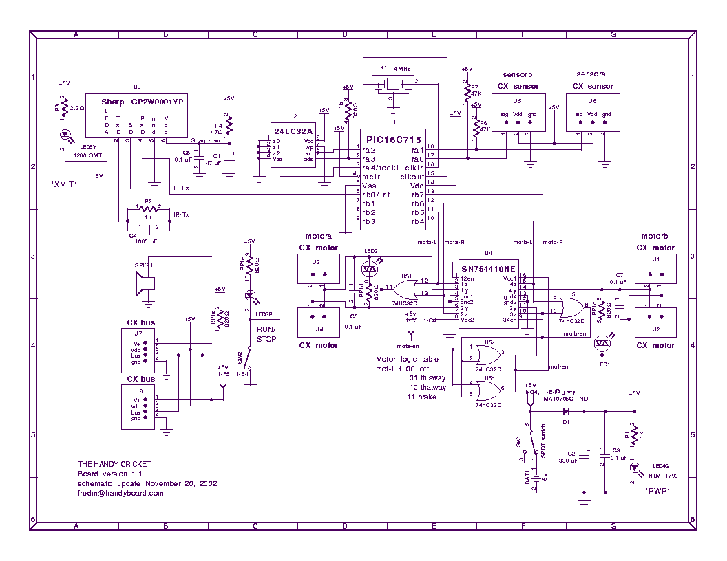
Handy Cricket Hardware Description
This document presents an overview of the hardware design of the Handy Cricket.
The Handy Cricket is a compact electronic device designed for educational and recreational purposes, primarily aimed at children. The hardware design incorporates various components that work together to...
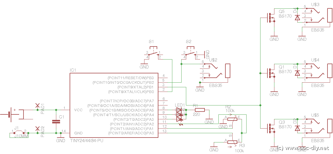
delay
This article outlines the construction of a simple microcontroller-based delay circuit designed for photographic applications, such as drop or high-speed photography. It is capable of controlling the trigger lag for cameras and flash units, generating periodic trigger pulses, or managing...
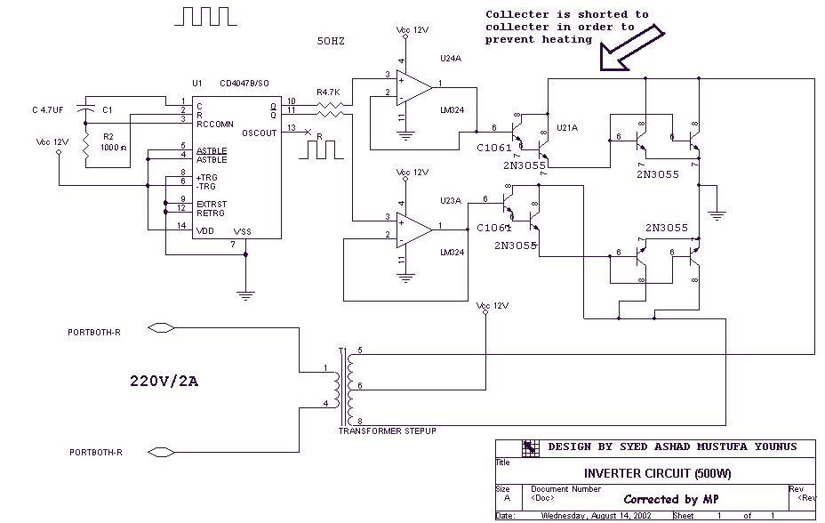
12-220V Power Inverter
Using this circuit you can convert the 12V dc into the 220V Ac. In this circuit, 4047 is used to generate the square wave of 50Hz and amplify the current and then amplify the voltage by using the step transformer....
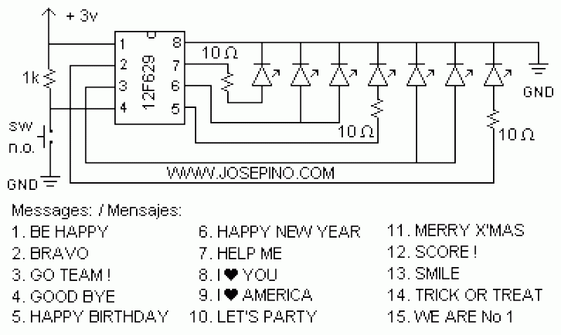
ON/OFF button using Microcontrollers
Using a switch to power up your microcontroller projects may not be a good idea if you need to "wake" the PIC during some events. For example: A metal detector sends a pulse indicating a car is ready to enter...
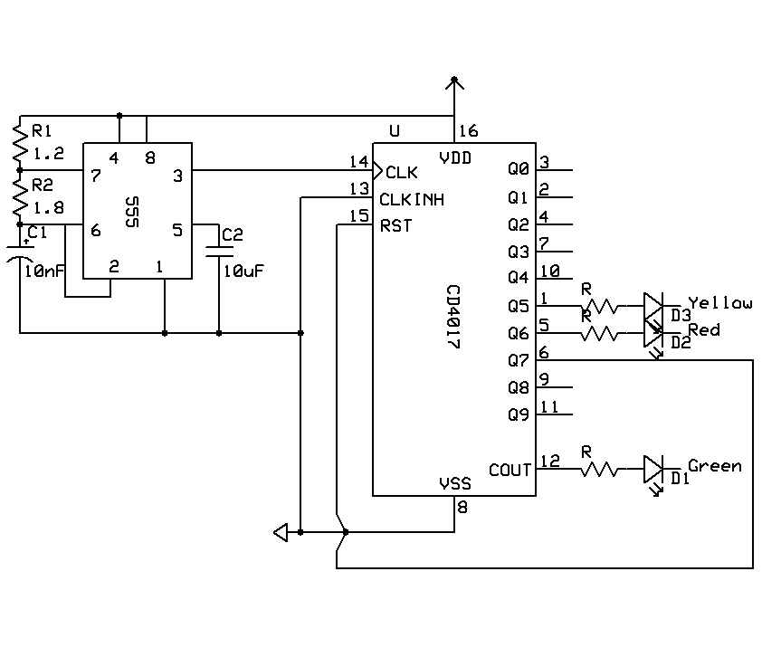
Training Boxing timer schematic
A timer is being developed for circuit training or boxing training. The timer does not require any external input, except for a reset function. The project can be simplified using a microcontroller, such as the PIC12F635, which is cost-effective at...
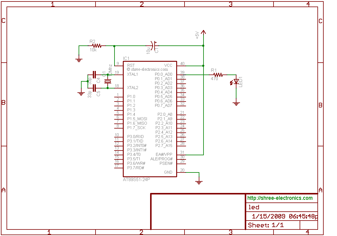
microcontroller led interfacing
The initial step often taken when learning about any microcontroller or embedded system is to make an LED blink. The circuit presented below illustrates the setup for interfacing an LED. Note: Due to the large dimensions of the circuit diagram,...