


Power Converter Topology and MOSFET for 48-V Telecom Systems
#power converter
#MOSFET
#telecom systems
#voltage regulation
#isolation
#48V
#3.3V
#2.5V
#transients
#high voltage
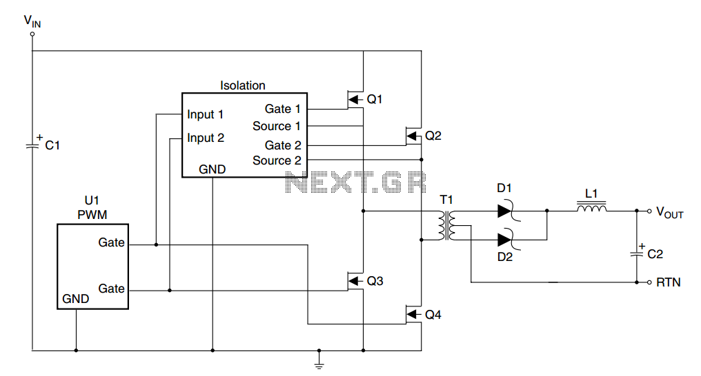
Description: A typical specification can range from a low of 36V to a high of 72V, with a nominal value of 48V. In some designs, transients exceeding 100V must be considered. Most of these designs will require input to output isolation of up to 1500V. Output voltages are frequently 5V and below, with 3.3V being the most common requirement, and 2.5V gaining in popularity. If a processor is present on the card, voltages as low as 1.3V are not uncommon. A common approach is to regulate a distributed power bus, such as the 5V rail, and then use non-isolated DC/DC converters to generate lower voltages. With the shift away from 5V, the 3.3V rail is beginning to serve as the distributed bus; however, from the perspective of the power supply designer, this situation is not ideal. Fairchild has recently introduced a family of high voltage MOSFETs with drain voltage specifications ranging from 80V to 200V. This application note will provide information helpful in the proper selection of FETs for primary side switches available in various types of 48V power converters.
In designing power conversion circuits, the specifications for input voltage, output voltage, and isolation are critical. A range of 36V to 72V with a nominal value of 48V is common in many applications, particularly in systems that may experience transients above 100V. The requirement for input-to-output isolation of up to 1500V ensures safety and reliability in high-voltage environments.
Output voltage requirements typically focus on lower voltages, with 3.3V and 2.5V becoming increasingly prevalent, especially in modern digital circuits where processors may operate at lower voltage levels, such as 1.3V. This necessitates a well-designed power distribution system that can effectively manage voltage regulation and conversion.
A common method for achieving this is through the regulation of a distributed power bus, often starting with a 5V rail. Non-isolated DC/DC converters can then be employed to step down this voltage to the required levels for various components. However, with the industry trend moving towards lower voltage systems, the 3.3V rail is emerging as a more prevalent distributed bus. This shift presents challenges for power supply designers, as the transition may not align with optimal design practices.
The introduction of high voltage MOSFETs by Fairchild, with specifications ranging from 80V to 200V, provides an essential tool for power supply designers. These MOSFETs can be utilized as primary side switches in various types of 48V power converters, enhancing the efficiency and performance of the overall power management system. Proper selection of these FETs is crucial to ensure that they meet the demands of the specific application while maintaining reliability and safety standards. This application note serves as a valuable resource for understanding the criteria for selecting the appropriate FETs for use in these power conversion designs.A typical specification can range from a low of 36V to a high of 72- with a 48-V nominal. In some designs, transients in excess of 100V need to be considered. Most of these designs will require input to output isolation of up to 1500V. Output voltages are frequently 5V and below with 3. 3V probably the most common requirement, and 2. 5V gaining in popularity. If a processor is on the card, voltages as low as 1. 3V are not unlikely. One common approach is to regulate a distributed power bus, say the 5V rail, and then use non-isolated DC/DC converters to generate lower voltages. With the tendency away from 5V, the 3. 3V rail is beginning to serve as the distributed bus, although, from the power supply designer`s perspective, this is not the most of desirable situations.
Fairchild has recently introduced a family of high voltage MOSFETs ranging from 80- to 200-V drain voltage specifications. This application note will provide information helpful in the proper selection of FETs for primary side switches available in various types of 48V power converters.
In designing power conversion circuits, the specifications for input voltage, output voltage, and isolation are critical. A range of 36V to 72V with a nominal value of 48V is common in many applications, particularly in systems that may experience transients above 100V. The requirement for input-to-output isolation of up to 1500V ensures safety and reliability in high-voltage environments.
Output voltage requirements typically focus on lower voltages, with 3.3V and 2.5V becoming increasingly prevalent, especially in modern digital circuits where processors may operate at lower voltage levels, such as 1.3V. This necessitates a well-designed power distribution system that can effectively manage voltage regulation and conversion.
A common method for achieving this is through the regulation of a distributed power bus, often starting with a 5V rail. Non-isolated DC/DC converters can then be employed to step down this voltage to the required levels for various components. However, with the industry trend moving towards lower voltage systems, the 3.3V rail is emerging as a more prevalent distributed bus. This shift presents challenges for power supply designers, as the transition may not align with optimal design practices.
The introduction of high voltage MOSFETs by Fairchild, with specifications ranging from 80V to 200V, provides an essential tool for power supply designers. These MOSFETs can be utilized as primary side switches in various types of 48V power converters, enhancing the efficiency and performance of the overall power management system. Proper selection of these FETs is crucial to ensure that they meet the demands of the specific application while maintaining reliability and safety standards. This application note serves as a valuable resource for understanding the criteria for selecting the appropriate FETs for use in these power conversion designs.A typical specification can range from a low of 36V to a high of 72- with a 48-V nominal. In some designs, transients in excess of 100V need to be considered. Most of these designs will require input to output isolation of up to 1500V. Output voltages are frequently 5V and below with 3. 3V probably the most common requirement, and 2. 5V gaining in popularity. If a processor is on the card, voltages as low as 1. 3V are not unlikely. One common approach is to regulate a distributed power bus, say the 5V rail, and then use non-isolated DC/DC converters to generate lower voltages. With the tendency away from 5V, the 3. 3V rail is beginning to serve as the distributed bus, although, from the power supply designer`s perspective, this is not the most of desirable situations.
Fairchild has recently introduced a family of high voltage MOSFETs ranging from 80- to 200-V drain voltage specifications. This application note will provide information helpful in the proper selection of FETs for primary side switches available in various types of 48V power converters.
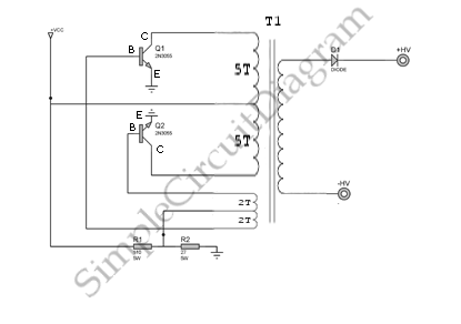
High Voltage Inverter
This is a simple high-voltage inverter circuit. It uses an NPN transistor type 2N3055. This circuit is designed to invert low voltage to high voltage.
The high-voltage inverter circuit utilizing the 2N3055 NPN transistor serves as an effective means to convert...
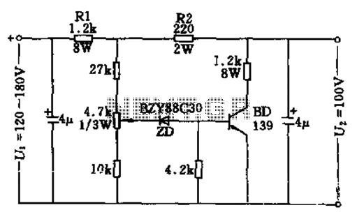
100v / 10ma regulator circuit
The circuit features no-load and short circuit protection mechanisms. To accommodate short circuit conditions, it is necessary to increase resistors R1 and R2 to allow for power dissipation; for example, R1 can be set to 1.2kΩ with a power rating...
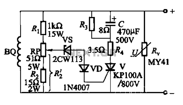
High voltage generator excitation set overvoltage protection circuit
The DC voltage for the generator field winding is supplied by a three-phase thyristor rectifier. In instances of incorrect operation, phase misalignment, or system failure, the rectifier may generate hazardous conditions, leading to over-voltage insulation issues on the DC side...
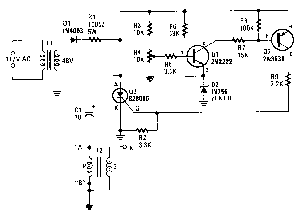
Capacitor-discharge-high-voltage-generator
A step-down transformer T1 reduces the incoming line voltage to approximately 48 Vac, which is then rectified by diode D1. The resulting direct current charges capacitor C1 through a current-limiting resistor R1 to a voltage level set by R4. When...
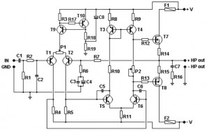
100w basic mosfet amplifier
This basic MOSFET amplifier is simple to construct and low-cost, making it ideal for Hi-Fi amplifiers and instrument amplifiers such as guitars and keyboards. It delivers an output power of ±100 W RMS at an 8-ohm load or ±160 W...
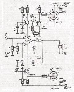
Electronics Mosfet power amplifier schematics
This simple MOSFET power audio amplifier circuit, featuring a TL071C operational amplifier and two MOSFET power amplifiers, can deliver up to 45W at an 8-ohm load. The schematic is based on Siliconix applications and incorporates variations in voltage across two...
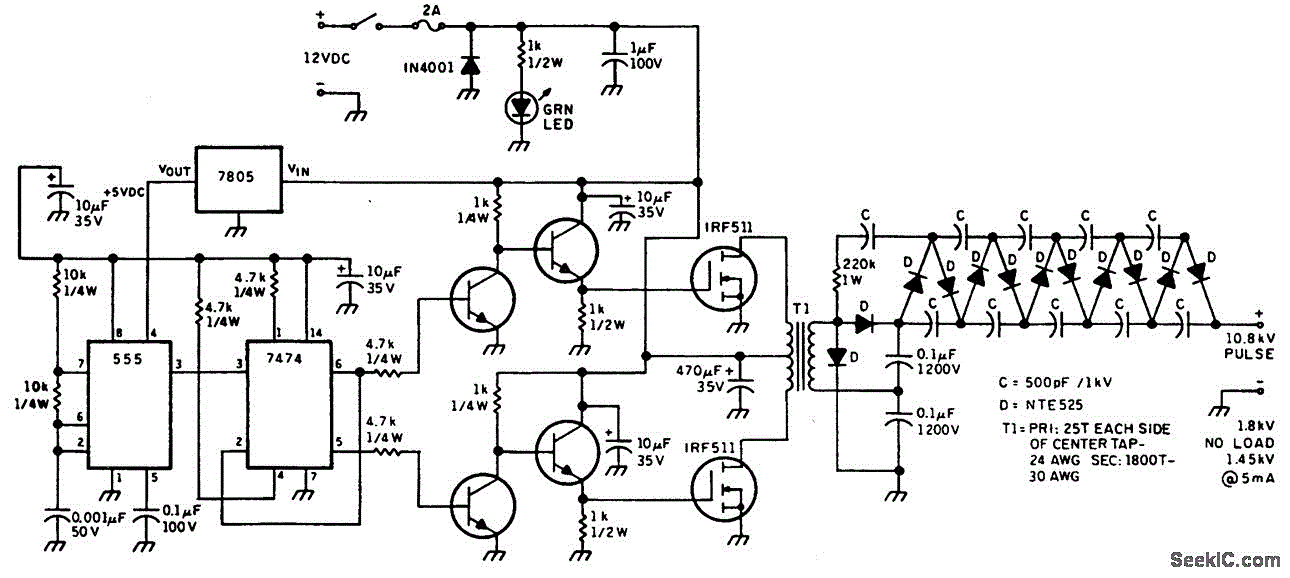
HELIUM NEON LASER SUPPLY
This figure illustrates a method for generating a momentary 10-kV voltage pulse to initiate plasma discharge across a laser tube. A diode voltage-multiplier circuit is connected in series with the main supply, obtaining its input power from one of the...
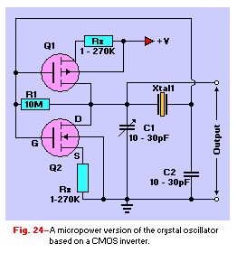
Transistor Tutorial MOSFETs
The Metal-Oxide-Semiconductor Field-Effect Transistor (MOSFET) is analogous to the Junction Field-Effect Transistor (JFET) in several aspects. Both types are voltage-driven unipolar devices that rely on either electron or hole movement, but not both, unlike bipolar transistors. A key structural distinction...
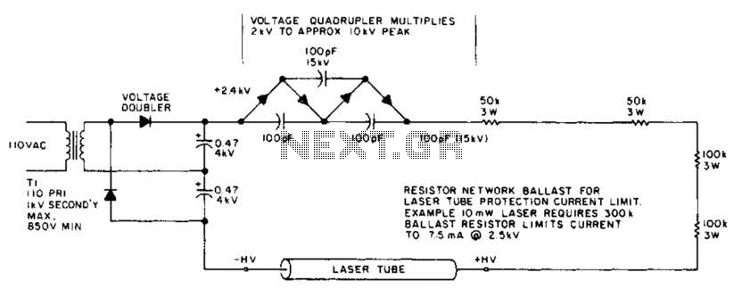
Laser Power Supply And Starting Circuit Circuit
This circuit delivers a peak voltage of 10 kV, while limiting the current to 7.5 mA at 2 kV. The resistors included in the design serve the purpose of ballasting. Additionally, the starting circuit is unable to sustain the 10...