


SIMPLE INVERTER CIRCUIT 230V
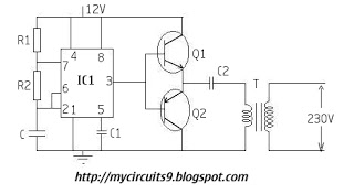
Description: The timer IC (NE555) is configured as an astable multivibrator in this circuit. It generates an alternating non-sinusoidal output waveform as soon as a supply voltage of 12V is applied. Therefore, alternating voltage is produced from direct current (battery). The output from these transistors is then fed to the input (primary) of a step-up transformer. This will upconvert the input voltage to the desired level of 230V.
The NE555 timer, when configured in the astable mode, operates continuously without any external triggering. It alternates between its high and low states, producing a square wave output. In this circuit, the frequency and duty cycle of the output waveform can be adjusted by changing the values of the timing resistors and capacitor connected to the NE555. The output frequency can be calculated using the formula:
\[ f = \frac{1.44}{(R1 + 2R2)C} \]
Where \( R1 \) and \( R2 \) are the resistances in ohms, and \( C \) is the capacitance in farads. This output is a square wave, which is suitable for driving a transformer.
The transistors in the circuit act as switches, amplifying the output from the NE555 timer to a level sufficient to drive the primary winding of the step-up transformer. When the transistors are turned on by the NE555 output, they allow current to flow through the primary winding of the transformer, inducing a higher voltage in the secondary winding due to the transformer's turns ratio.
The step-up transformer is critical in converting the low voltage (12V) output from the circuit to a higher voltage level (230V) suitable for various applications, such as powering AC devices. The transformer must be rated appropriately to handle the power requirements and ensure safe operation.
Overall, this circuit effectively demonstrates the conversion of direct current into a higher alternating voltage using a timer IC, transistors, and a step-up transformer, making it a valuable design for applications requiring voltage amplification.The timer IC(NE555) is wired as an ASTABLE MULTIVIBRATOR in this circuit. It will generate Alternating non sinusoidal output wave form at the instant we giving supply Voltage(12V). Thus primarily we generated Alternating Voltage from direct Current (Battery). The output from these transistors are again fed to the input(primary) of a Stepup Transformer. This will upconvert the input Voltage to desired level (230V).
The NE555 timer, when configured in the astable mode, operates continuously without any external triggering. It alternates between its high and low states, producing a square wave output. In this circuit, the frequency and duty cycle of the output waveform can be adjusted by changing the values of the timing resistors and capacitor connected to the NE555. The output frequency can be calculated using the formula:
\[ f = \frac{1.44}{(R1 + 2R2)C} \]
Where \( R1 \) and \( R2 \) are the resistances in ohms, and \( C \) is the capacitance in farads. This output is a square wave, which is suitable for driving a transformer.
The transistors in the circuit act as switches, amplifying the output from the NE555 timer to a level sufficient to drive the primary winding of the step-up transformer. When the transistors are turned on by the NE555 output, they allow current to flow through the primary winding of the transformer, inducing a higher voltage in the secondary winding due to the transformer's turns ratio.
The step-up transformer is critical in converting the low voltage (12V) output from the circuit to a higher voltage level (230V) suitable for various applications, such as powering AC devices. The transformer must be rated appropriately to handle the power requirements and ensure safe operation.
Overall, this circuit effectively demonstrates the conversion of direct current into a higher alternating voltage using a timer IC, transistors, and a step-up transformer, making it a valuable design for applications requiring voltage amplification.The timer IC(NE555) is wired as an ASTABLE MULTIVIBRATOR in this circuit. It will generate Alternating non sinusoidal output wave form at the instant we giving supply Voltage(12V). Thus primarily we generated Alternating Voltage from direct Current (Battery). The output from these transistors are again fed to the input(primary) of a Stepup Transformer. This will upconvert the input Voltage to desired level (230V).
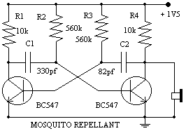
Mosquito repelant circuit
The Astable Multivibrator, which is generally used as a signal generator, is once again used here to generate the desired frequencies. It is an excellent example of the fact, how versatile simple basic electronic circuit can be. It seems quite...
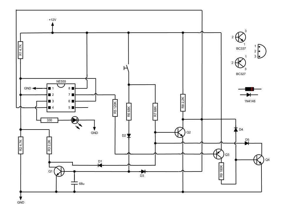
Toggle on off switch
This circuit toggles on and off a NE555 with a single momentary switch. Unlike a mechanical bistable relay the circuit backs to the start condition if you switch off the power supply. No relay contact is used. This circuit could...
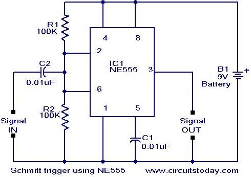
Scmitt Trigger circuit using NE 555
In addition to its timing functions, the two comparators of the 555 timer can be utilized independently for various applications. One such application is a Schmitt Trigger. The inputs of the two comparators (pin 2 and pin 6) are connected...
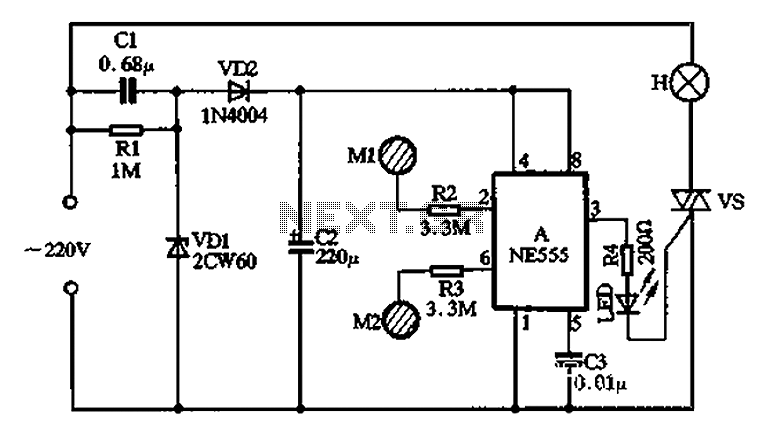
With NE555 make double touch light switch 1
The circuit operates using a touch electrode integrated with a base NE555, forming a double touch light switch circuit. It consists of several parts, including a simple capacitive buck converter with components Cl, C2, VDI, and VD2, which together create...
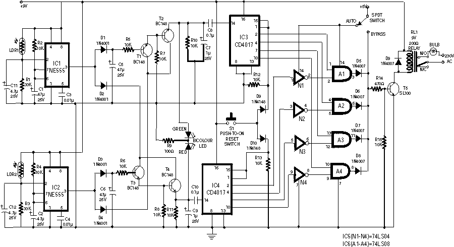
Automatic Room Lights With NE555 IC
This circuit illustrates an automatic room light circuit diagram. It features a small memory component that allows it to automatically switch on and off.
The automatic room light circuit is designed to enhance energy efficiency and convenience by utilizing a memory...
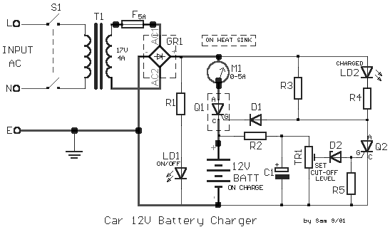
12V Car Battery Charger circuit
The following circuit diagram represents a battery charger designed for a 12V car battery. This circuit includes overcharging protection, which automatically disconnects the charging circuit. Unlike typical battery chargers that continuously supply a few amperes to the battery while powered...
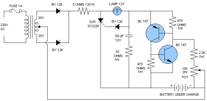
car battery charger
A car battery charger schematic and description. This 12V automatic car battery charger circuit can also be used for charging other automobile batteries.
The described circuit is a 12V automatic car battery charger designed for efficient charging of various automobile batteries....
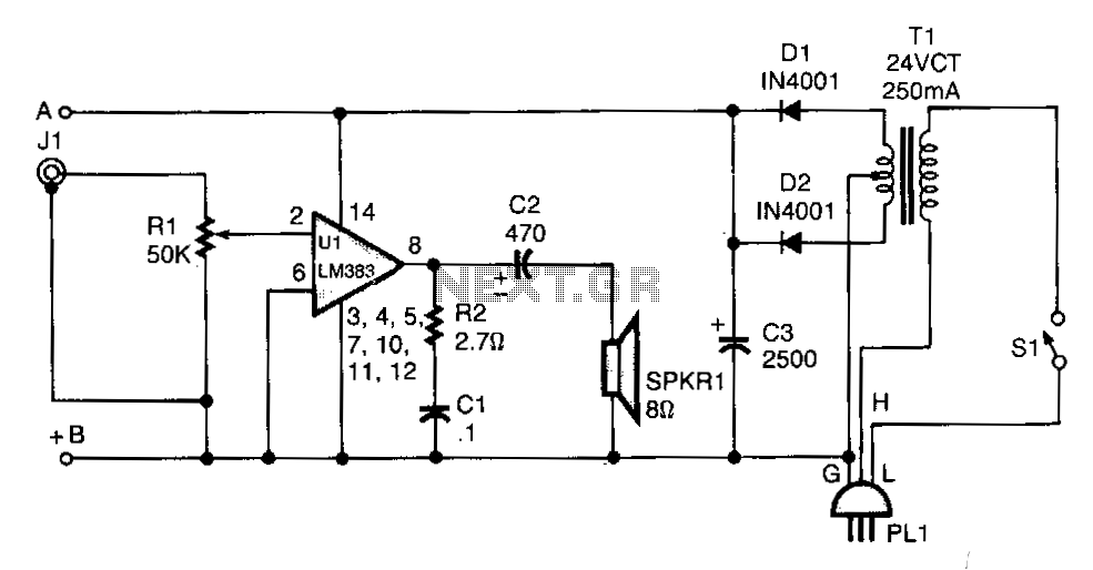
Line-operated-amplifier
T1 isolates the unit from the line and has a 24-V, center-tapped secondary. The output of the transformer is rectified by diodes D1 and D2 and filtered by capacitor C3 to provide 15 to 18 Vdc. The LM383 has built-in...
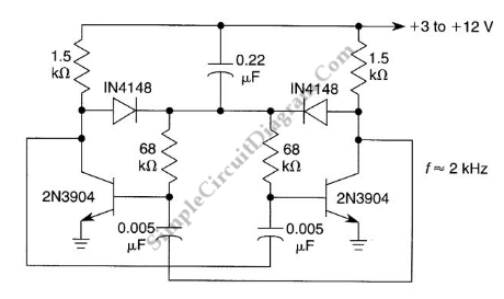
Starting Network for Astable Multivibrator
An astable multivibrator is a flip-flop that produces two unstable states (high and low), functioning as an oscillator.
An astable multivibrator is a fundamental electronic circuit that continuously switches between its two states without requiring any external triggering signals. This...