


Simple PWM inverter circuit diagram using PWM chip SG3524
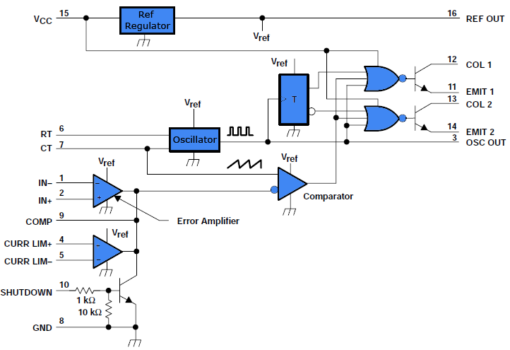
Description: This document outlines a simple PWM (Pulse Width Modulation) DC to AC voltage inverter circuit based on the SG3524 integrated circuit. The SG3524 is a fixed frequency PWM voltage regulator control circuit that offers indifferent outputs suitable for both single-ended and push-pull applications. This integrated circuit includes all necessary functions to produce a regulating power supply, electrical inverter, or switching regulator on a single chip. It can also serve as a control element for high power output applications. The principle of pulse width modulation involves adjusting the width of pulses in a pulse train relative to a control signal, where an increase in control voltage results in wider pulses. By using a sinusoidal frequency as the control voltage for PWM circuits, it is possible to generate a high power waveform with an average voltage that varies in accordance with the sine wave, making it suitable for driving AC loads. The complementary output configuration supports both single-ended and push-pull applications. Each SG3524 device includes an on-chip regulator, error amplifier, programmable oscillator, pulse-steering flip-flop, two uncommitted pass transistors, a high-gain comparator, and current-limiting and shutdown circuitry. The internal reference voltage can be divided externally by a resistor network to provide a reference for the built-in error amplifier, with the option to use an external reference as well. The output voltage is sensed through a resistor divider network, and the error signal is amplified. This amplified voltage is compared with a linear voltage ramp at the timing capacitor (CT), resulting in a PWM pulse. The PWM pulse generated by the comparator is directed to the corresponding output pass transistors (Q1, Q2) via the pulse steering flip-flop, which is toggled synchronously by the oscillator output. The oscillator output pulse also serves as an inhibiting pulse to ensure that both transistors do not turn ON simultaneously. The duration of this pulse is determined by the value of CT. When pin 11 of the IC goes high, the lower transistor is activated, allowing current to flow from the +12V source through the lower half of the transformer primary to ground.
The SG3524 IC is designed for versatility in various applications, particularly in power electronics. Its ability to operate in both single-ended and push-pull configurations makes it suitable for driving transformers in inverter circuits, which are essential for converting DC power into AC power for various applications, including renewable energy systems and motor drives. The integrated error amplifier facilitates precise voltage regulation, ensuring that the output remains stable despite variations in input voltage or load conditions.
The programmable oscillator within the SG3524 allows for adjustment of the switching frequency, which is critical for optimizing the efficiency and performance of the inverter. The use of a timing capacitor (CT) not only influences the frequency but also plays a crucial role in determining the pulse width modulation characteristics, directly affecting the output waveform's quality.
The implementation of a pulse-steering flip-flop ensures that the outputs are complementary, thus enhancing the efficiency of the inverter by minimizing losses associated with simultaneous conduction of both transistors. This design feature is particularly important in high-power applications where heat dissipation and efficiency are paramount.
To achieve the desired output waveform, careful selection of external components, such as the resistor divider network for voltage sensing and the timing capacitor, is essential. This allows for fine-tuning of the PWM characteristics to match the requirements of specific AC loads. Overall, the SG3524-based inverter circuit exemplifies a robust solution for efficient DC to AC power conversion, with a range of applications in both consumer electronics and industrial systems.Here is a simple PWM dc to ac voltage inverter circuit based on IC SG 3524. The SG3524 IC chips is a fixed frequency PWM (Pulse Width Modulation) voltage regulator control circuit, with indifferent outputs for single ended or push pull applications. The SG3524 IC integrated circuit has all the functions necessary for the production of a regulating power supply, electrical inverteror switching regulator on a single chip. Moreover it can be used as the control element for high power output purposes. We know pulse width modulation PWM theory, i. e. a method of adjusting the width of the pulses in a pulse train relative to a control signal. If greater the control voltage, wider is the resultant pulses. Using a sinusoidal frequency as the control voltage for pulse width modulator circuits, it is likely to generate a high power waveform whose average voltage varies with the sine wave, which is suitable for driving ac loads. The complementary output allows either single-ended or push-pull application. Each device includes an on-chip regulator, error amplifier, programmable oscillator, pulse-steering flip-flop, two uncommitted pass transistors, a high-gain comparator, current-limiting and shutdown circuitry.
The inside reference voltage is divided on the outside by a resistor network to give a reference to inbuilt error amplifier. (External reference can also be used). The output is sensed by a subsequent resistor divider network and the error signal is amplified. This voltage is then compared with the linear voltage ramp at timing capacitor CT, thus producing a pulse width modulation (PWM) pulse.
The resultant PWM pulse from the comparator is passed to the corresponding output pass transistor (Q1, Q2 refer block diagram) using the pulse steering flip flop, which is synchronously toggled by the oscillator output. The oscillator output pulse also acts as an inhibiting pulse to make sure that both the transistors are never turned ON simultaneously.
The duration of this pulse is determined by the value of CT. When 11 of the IC pin goes high, lower transistor gets switched ON and current flows from the +12V source via the lower half of the transformer primary and sinks to the ground.
The SG3524 IC is designed for versatility in various applications, particularly in power electronics. Its ability to operate in both single-ended and push-pull configurations makes it suitable for driving transformers in inverter circuits, which are essential for converting DC power into AC power for various applications, including renewable energy systems and motor drives. The integrated error amplifier facilitates precise voltage regulation, ensuring that the output remains stable despite variations in input voltage or load conditions.
The programmable oscillator within the SG3524 allows for adjustment of the switching frequency, which is critical for optimizing the efficiency and performance of the inverter. The use of a timing capacitor (CT) not only influences the frequency but also plays a crucial role in determining the pulse width modulation characteristics, directly affecting the output waveform's quality.
The implementation of a pulse-steering flip-flop ensures that the outputs are complementary, thus enhancing the efficiency of the inverter by minimizing losses associated with simultaneous conduction of both transistors. This design feature is particularly important in high-power applications where heat dissipation and efficiency are paramount.
To achieve the desired output waveform, careful selection of external components, such as the resistor divider network for voltage sensing and the timing capacitor, is essential. This allows for fine-tuning of the PWM characteristics to match the requirements of specific AC loads. Overall, the SG3524-based inverter circuit exemplifies a robust solution for efficient DC to AC power conversion, with a range of applications in both consumer electronics and industrial systems.Here is a simple PWM dc to ac voltage inverter circuit based on IC SG 3524. The SG3524 IC chips is a fixed frequency PWM (Pulse Width Modulation) voltage regulator control circuit, with indifferent outputs for single ended or push pull applications. The SG3524 IC integrated circuit has all the functions necessary for the production of a regulating power supply, electrical inverteror switching regulator on a single chip. Moreover it can be used as the control element for high power output purposes. We know pulse width modulation PWM theory, i. e. a method of adjusting the width of the pulses in a pulse train relative to a control signal. If greater the control voltage, wider is the resultant pulses. Using a sinusoidal frequency as the control voltage for pulse width modulator circuits, it is likely to generate a high power waveform whose average voltage varies with the sine wave, which is suitable for driving ac loads. The complementary output allows either single-ended or push-pull application. Each device includes an on-chip regulator, error amplifier, programmable oscillator, pulse-steering flip-flop, two uncommitted pass transistors, a high-gain comparator, current-limiting and shutdown circuitry.
The inside reference voltage is divided on the outside by a resistor network to give a reference to inbuilt error amplifier. (External reference can also be used). The output is sensed by a subsequent resistor divider network and the error signal is amplified. This voltage is then compared with the linear voltage ramp at timing capacitor CT, thus producing a pulse width modulation (PWM) pulse.
The resultant PWM pulse from the comparator is passed to the corresponding output pass transistor (Q1, Q2 refer block diagram) using the pulse steering flip flop, which is synchronously toggled by the oscillator output. The oscillator output pulse also acts as an inhibiting pulse to make sure that both the transistors are never turned ON simultaneously.
The duration of this pulse is determined by the value of CT. When 11 of the IC pin goes high, lower transistor gets switched ON and current flows from the +12V source via the lower half of the transformer primary and sinks to the ground.
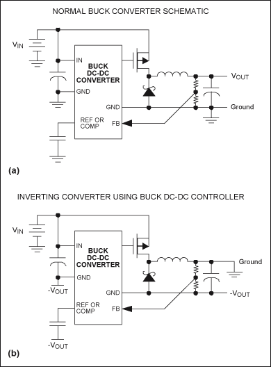
Making a Voltage Inverter from a Buck (Step-Down) DC-DC Converter
Any step-down DC-DC converter can be utilized as an inverter without modifications to the operating schematic. The only differences between the standard step-down application and the inverting operation are the labels of the connection points. The step-down VOUT is...
A step-down...
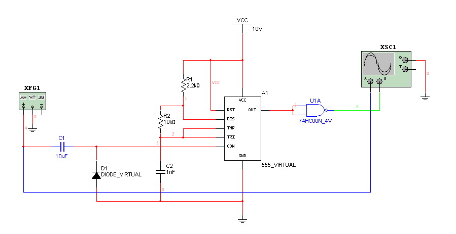
really need help on PWM and PPM circuit
Hello everyone. I need some help. I have constructed a PWM and PPM circuit. The output is functioning smoothly, but I am experiencing some problems and I am not very experienced.
The PWM (Pulse Width Modulation) and PPM (Pulse Position Modulation)...
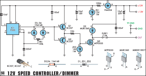
12V Speed Controller/Dimmer
This circuit serves as a speed controller for a 12V motor rated up to 5A (continuous) or as a dimmer for a 12V halogen or standard incandescent lamp rated up to 50W. It modulates the power to the load (motor...
PWM tutoria
PWM circuits are versatile. They can be used to dim LEDs, regulate the speed of fans and motors, control the power supplied to thermoelectric coolers, or manage the power to nearly any device. It is essential to ensure that the...
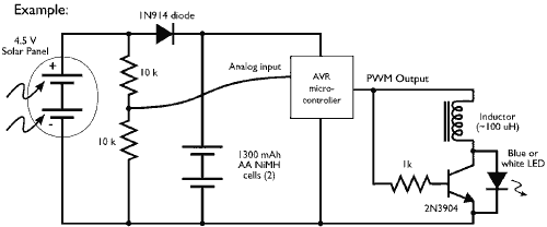
Microcontroller driving a Joule Thief circuit
This example demonstrates the PWM (pulse-width modulation) output of a microcontroller controlling a Joule Thief style voltage booster to power a white LED.
The circuit described utilizes a microcontroller to generate a PWM signal, which is an effective method for controlling...
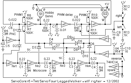
Servocore 2-motor walker circuit
There is an advantage in using continuously active PWM signals. The main reason is that the asynchronous frequencies of the PWM core and microcore can sometimes result in a shortened PWM pulse. The servo recognizes this as a command for...
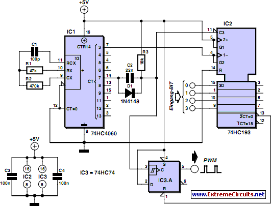
Discrete PWM Generator Circuit
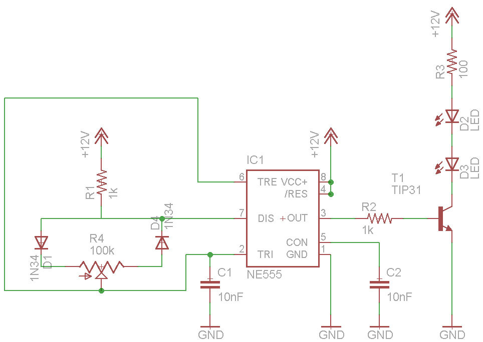
PWM waveforms are frequently employed to regulate the speed of DC motors. The mark/space ratio of the digital waveform can be established either by utilizing an adjustable analog voltage level (as seen in a NE555-based PWM generator) or through digital...
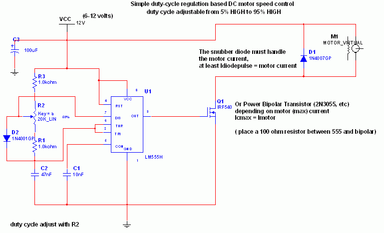
Simple DC motor PWM speed control
The 555 IC is configured as an astable multivibrator, producing a constant frequency independent of the duty cycle. The total resistance (R_charge + R_discharge, with the diode in consideration) remains constant at 22 kΩ, resulting in a frequency of approximately...
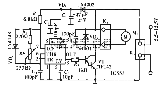
PWM DC motor speed control circuit
The circuit operates using pulse position modulation, which is a method distinct from the more commonly utilized pulse width modulation for speed control. A 555 timer is employed as a square wave modulator, generating output pulses with a fixed width...