


Three Phase 6 Pulse Inverter
#three phase
#inverter
#Arduino
#transistors
#motor control
#AC/DC
#power electronics
#generator
#pulse width modulation
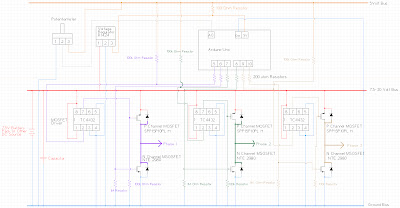
Description: One of the primary objectives was to convert a generator into a motor using an Arduino. The process of transforming a simple generator into a motor proved to be particularly challenging with a three-phase generator, necessitating the creation of a three-phase inverter. The initial assumption was that the circuit would be straightforward, requiring only a few transistors and diodes. However, it became evident that the schematic lacked crucial details, leading to confusion over several weeks. Specifically, the transistors connected to the high side required additional circuitry to function properly. The components involved include six 200-ohm resistors (though 100-ohm and 4000-ohm resistors were used due to a shortage), three TC4432 MOSFET driver chips—caution is advised as half of these were defective, possibly due to static or quality control issues, and an alternative MOSFET driver may be necessary for voltages above 30V, or a charge pump circuit may be considered. Additionally, a 7805A R1424 voltage regulator supplies power to the Arduino from a battery pack, although the onboard voltage regulator could be an alternative. A non-electrolytic capacitor, the label of which was illegible, was used to mitigate ripple on the DC side of the inverter. The battery pack consists of six rechargeable 1.25V batteries, and the circuit can also operate using a 20V DC supply; however, pin 3 on the TC4432s must be disconnected from ground, and the voltage regulator should be replaced with a separate DC source for the Arduino to prevent overheating. Above 30 volts, the circuit requires a redesign.
The circuit design for the three-phase inverter involves several key components that work together to convert DC power from the battery pack into a three-phase AC output suitable for driving a motor. The heart of the inverter consists of three pairs of transistors configured in a half-bridge arrangement. Each transistor pair is responsible for switching the current through the motor windings, creating the necessary phase shifts for three-phase operation.
The TC4432 MOSFET driver chips are crucial for driving the gates of the MOSFETs, ensuring that they switch on and off rapidly to minimize losses. It is vital to ensure that the MOSFET drivers are rated for the voltage levels being used; if the system operates above 30V, a more robust driver must be integrated into the design.
The resistors connected to the gate of the MOSFETs play a significant role in controlling the turn-on and turn-off characteristics, which affect the overall efficiency and performance of the inverter. A careful selection of resistor values is recommended to optimize switching times and prevent oscillations that could lead to MOSFET failure.
The voltage regulator (7805A R1424) is employed to provide a stable 5V supply to the Arduino for reliable operation. This regulator must be properly heat-sinked, especially when drawing significant current, to prevent thermal shutdown during operation.
The non-electrolytic capacitor serves to smooth out voltage ripples that can occur on the DC side of the inverter, ensuring a cleaner input signal to the switching circuitry. The selection of this capacitor should be based on its voltage rating and capacitance value to effectively filter noise without introducing significant lag in the response time.
Lastly, the battery pack configuration is critical for providing sufficient voltage and current to the inverter. The use of six rechargeable 1.25V batteries in series yields a nominal voltage of 7.5V, which is suitable for low-voltage applications. However, when using a higher voltage supply, careful attention must be paid to the connections and power supply to avoid damaging components or causing overheating.
In summary, the design of a three-phase inverter using an Arduino involves meticulous planning and component selection to ensure reliability and efficiency in converting DC power to three-phase AC power. Each component's role must be understood and integrated into the overall circuit to achieve successful operation.One of the primary things i wanted to do with my Arduino was turn my generators into motors. My simple generators were not simple to turn into motors but this proved to be particularly tricky with my three phase generator. Doing this requires me to create a three phase inverter. The first time I looked at a circuit for this, I thought it would be dead simple. All I need is a few transistors and a few diodes then I can hook them up like this: and it would work. This turned out to be untrue. That diagram really leaves out a whole lot of details which had me scratching my head for weeks. In particular the transistors connected to the high side just will not work without additional circuitry. 6- 200 ohm resistors (actually I ran out of these and used 100 ohm and 4000 ohm resistors from the output of the MOSFETs to the Arduino Uno, but 200 ohm are probably a better choice) 3- TC4432 MOSFET driver chip.
Be really careful with these, not sure if it was static on my part or poor quality control from the supplier but half of these didn`t work. If you want a inverter above 30V this component will need to be replaced with a different MOSFET driver.
Another alternative might be a charge pump circuit. 1- 7805A R1424 Voltage regulator. This powers the Arduino from the battery pack. The onboard voltage regulator on the arduino could probably substitute for this. 1- capacitor. Unfortunately this didn`t have a legible label on it so I am not quite sure what I used beyond that it was not an electrolytic capacitor so it was probably fairly low capacitance. This was just to lower any ripple which occurred on the DC side of the inverter. 1- battery pack with six rechargeable 1. 25 volt batteries. I also ran this circuit using a 20V DC supply but if you do this pin 3 on the TC4432s must be disconnected from ground and the voltage regulator must be replaced with a separate DC source to power the Arduino or the voltage regulator will overheat.
Above 30 Volts the circuit will need to be redesigned.
The circuit design for the three-phase inverter involves several key components that work together to convert DC power from the battery pack into a three-phase AC output suitable for driving a motor. The heart of the inverter consists of three pairs of transistors configured in a half-bridge arrangement. Each transistor pair is responsible for switching the current through the motor windings, creating the necessary phase shifts for three-phase operation.
The TC4432 MOSFET driver chips are crucial for driving the gates of the MOSFETs, ensuring that they switch on and off rapidly to minimize losses. It is vital to ensure that the MOSFET drivers are rated for the voltage levels being used; if the system operates above 30V, a more robust driver must be integrated into the design.
The resistors connected to the gate of the MOSFETs play a significant role in controlling the turn-on and turn-off characteristics, which affect the overall efficiency and performance of the inverter. A careful selection of resistor values is recommended to optimize switching times and prevent oscillations that could lead to MOSFET failure.
The voltage regulator (7805A R1424) is employed to provide a stable 5V supply to the Arduino for reliable operation. This regulator must be properly heat-sinked, especially when drawing significant current, to prevent thermal shutdown during operation.
The non-electrolytic capacitor serves to smooth out voltage ripples that can occur on the DC side of the inverter, ensuring a cleaner input signal to the switching circuitry. The selection of this capacitor should be based on its voltage rating and capacitance value to effectively filter noise without introducing significant lag in the response time.
Lastly, the battery pack configuration is critical for providing sufficient voltage and current to the inverter. The use of six rechargeable 1.25V batteries in series yields a nominal voltage of 7.5V, which is suitable for low-voltage applications. However, when using a higher voltage supply, careful attention must be paid to the connections and power supply to avoid damaging components or causing overheating.
In summary, the design of a three-phase inverter using an Arduino involves meticulous planning and component selection to ensure reliability and efficiency in converting DC power to three-phase AC power. Each component's role must be understood and integrated into the overall circuit to achieve successful operation.One of the primary things i wanted to do with my Arduino was turn my generators into motors. My simple generators were not simple to turn into motors but this proved to be particularly tricky with my three phase generator. Doing this requires me to create a three phase inverter. The first time I looked at a circuit for this, I thought it would be dead simple. All I need is a few transistors and a few diodes then I can hook them up like this: and it would work. This turned out to be untrue. That diagram really leaves out a whole lot of details which had me scratching my head for weeks. In particular the transistors connected to the high side just will not work without additional circuitry. 6- 200 ohm resistors (actually I ran out of these and used 100 ohm and 4000 ohm resistors from the output of the MOSFETs to the Arduino Uno, but 200 ohm are probably a better choice) 3- TC4432 MOSFET driver chip.
Be really careful with these, not sure if it was static on my part or poor quality control from the supplier but half of these didn`t work. If you want a inverter above 30V this component will need to be replaced with a different MOSFET driver.
Another alternative might be a charge pump circuit. 1- 7805A R1424 Voltage regulator. This powers the Arduino from the battery pack. The onboard voltage regulator on the arduino could probably substitute for this. 1- capacitor. Unfortunately this didn`t have a legible label on it so I am not quite sure what I used beyond that it was not an electrolytic capacitor so it was probably fairly low capacitance. This was just to lower any ripple which occurred on the DC side of the inverter. 1- battery pack with six rechargeable 1. 25 volt batteries. I also ran this circuit using a 20V DC supply but if you do this pin 3 on the TC4432s must be disconnected from ground and the voltage regulator must be replaced with a separate DC source to power the Arduino or the voltage regulator will overheat.
Above 30 Volts the circuit will need to be redesigned.
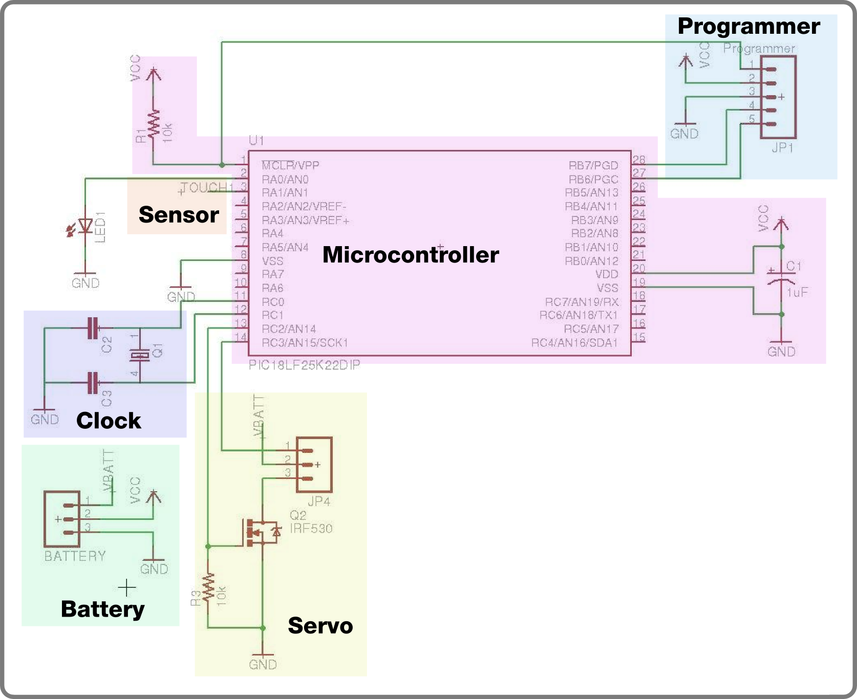
series robot circuit
For the second build in the Make It Last Build Series, a robotic plant is being constructed. This week focuses on assembling the control circuit, which will be used in future weeks to animate the plant. The basic circuit will...
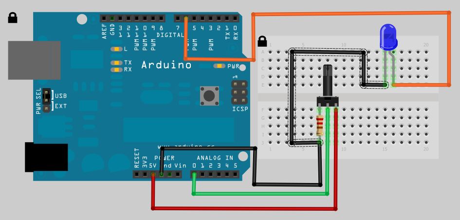
Arduino Analog Read Potentiometer to Digital Out LED
The analog to digital sketches have been extensively covered using various components. To progress to more complex circuits and concepts, it is essential to understand these simpler ones. This tutorial will not delve as deeply as others due to the...
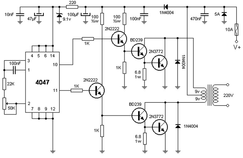
100W inverter 12V to 220VAC
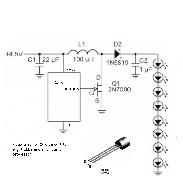
To lower or raise a specific voltage, a transformer is typically used; however, this component does not operate with direct current, which is available in batteries or vehicles. Therefore, an oscillator is required to generate alternating current. The integrated circuit...
Embedded Development on OSX
Fixed some issues with the Benito Arduino programmer and upgraded it to the latest version of the LUFA library. There was a mismatch between the INF file and the library-supplied descriptors. Apologies to the two XP users. As this is...
Pressure Activated Light-Up Umbrella using an Arduino
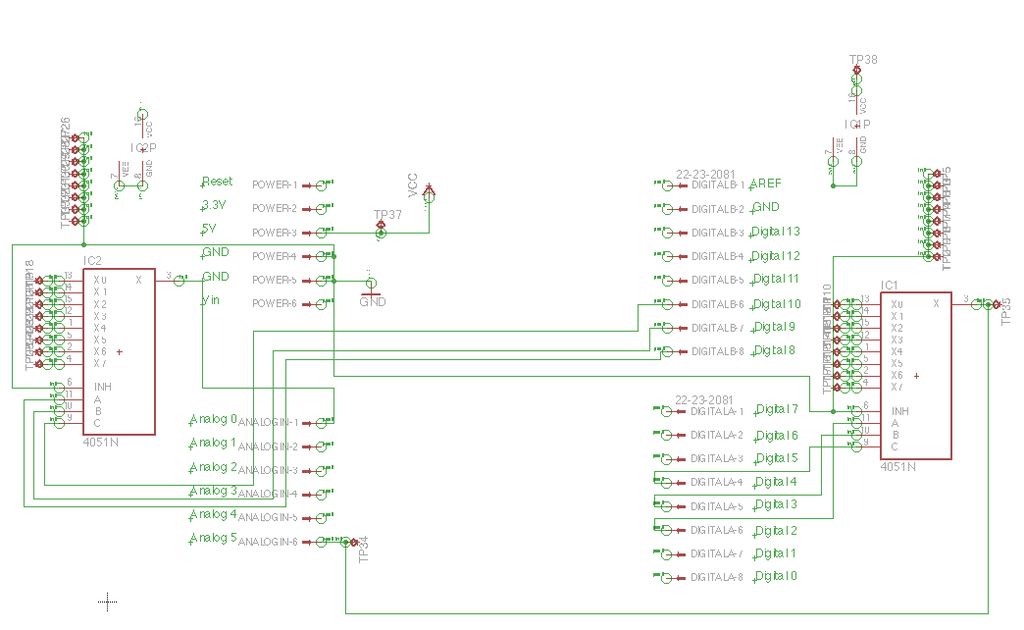
Inspired by a previous project, a unique design was developed that incorporates an umbrella capable of playing musical notes when pressed. For additional information regarding the 4051 chip, which functions as a multiplexer or demultiplexer, refer to resources available on...
Pimp Your Chocolates with Arduino IDE and ATTiny13
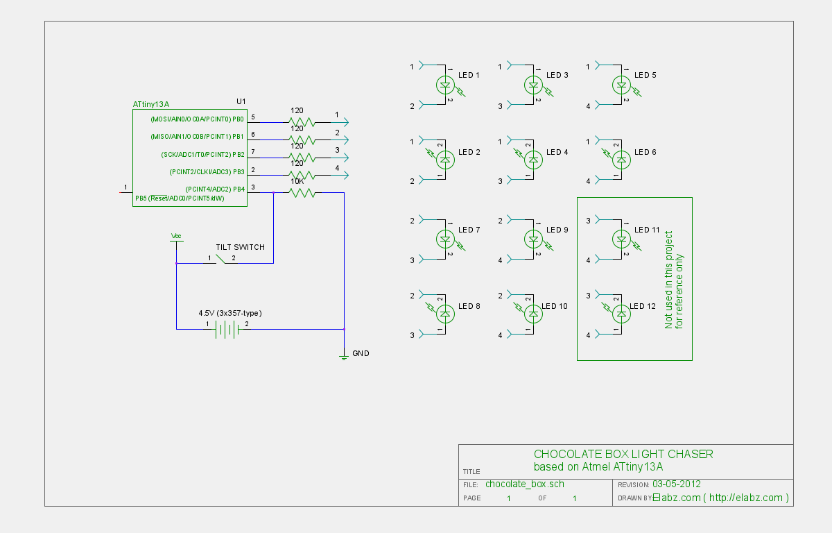
Transform a standard chocolate box into an impressive LED blinking display using an ATTiny13 AVR microcontroller, Arduino IDE, and several electronic components.
The project involves creating an eye-catching LED display housed within a chocolate box. The core of the circuit is...
Wheelchair Obstacle Avoidance System
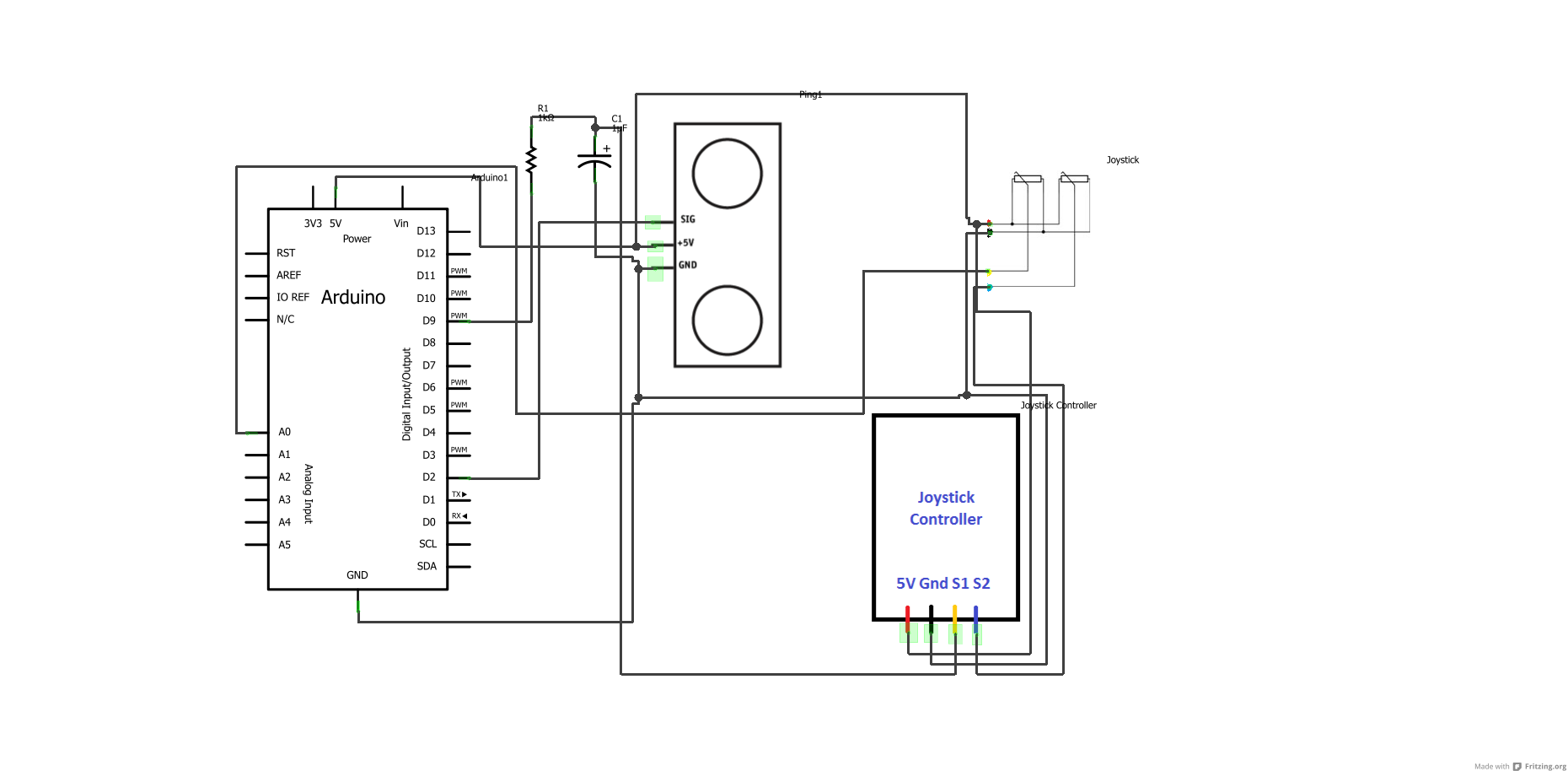
First, download any version of the Arduino software (the latest version is recommended) using the provided link, and then download the specified Arduino sketches. After the download is complete, open the sketches to view the written code. Complete the circuit...
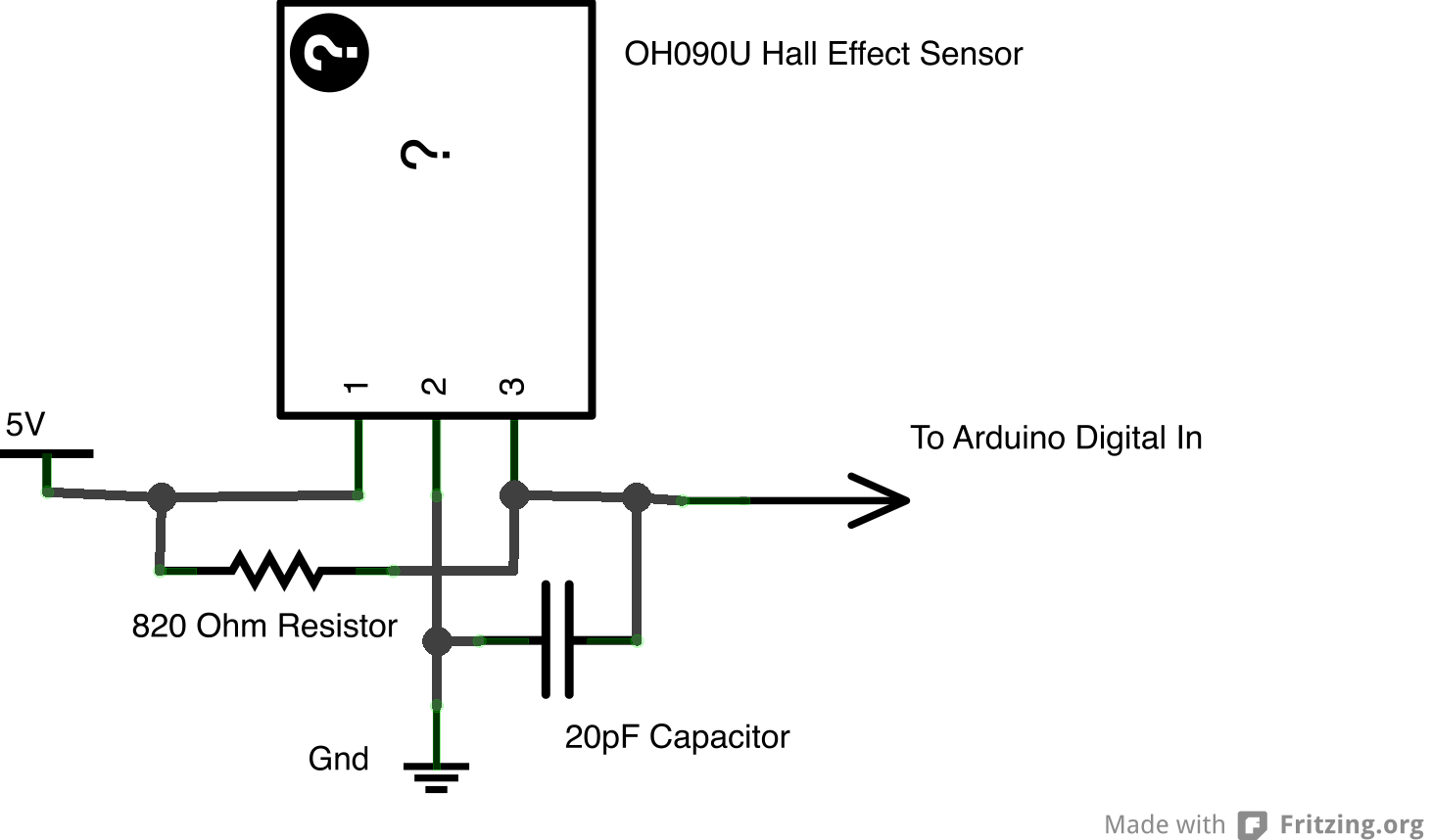
sensors
Although the Arduino effectively captures incoming sensor data, executing code typically in the microsecond range, challenges arose in transmitting data between the Arduino and Max. The data transfer speed was insufficient. The focus was primarily on creative project realization rather...
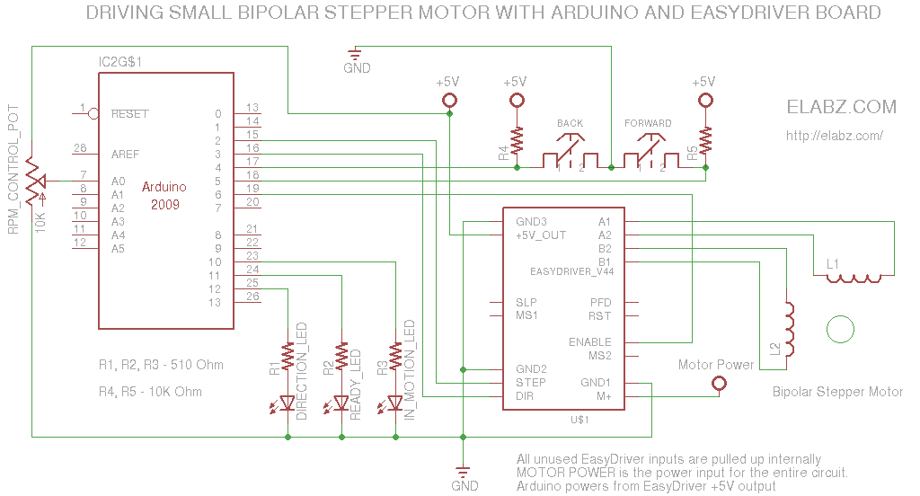
Manually controlling bipolar stepper motor with Arduino and EasyDriver
A simple circuit designed for testing bipolar stepper motors or for manual positioning using stepper motors. Schematics, Arduino sketch, and video are available.
This circuit serves as a versatile tool for both testing and controlling bipolar stepper motors, which are commonly...