


voltage conversion circuit composed of VFC320
#VFC320
#voltage conversion
#frequency converter
#pulse generator
#logic interface
#signal counter
#voltage to frequency
#frequency to voltage
#analog conversion
#signal processing
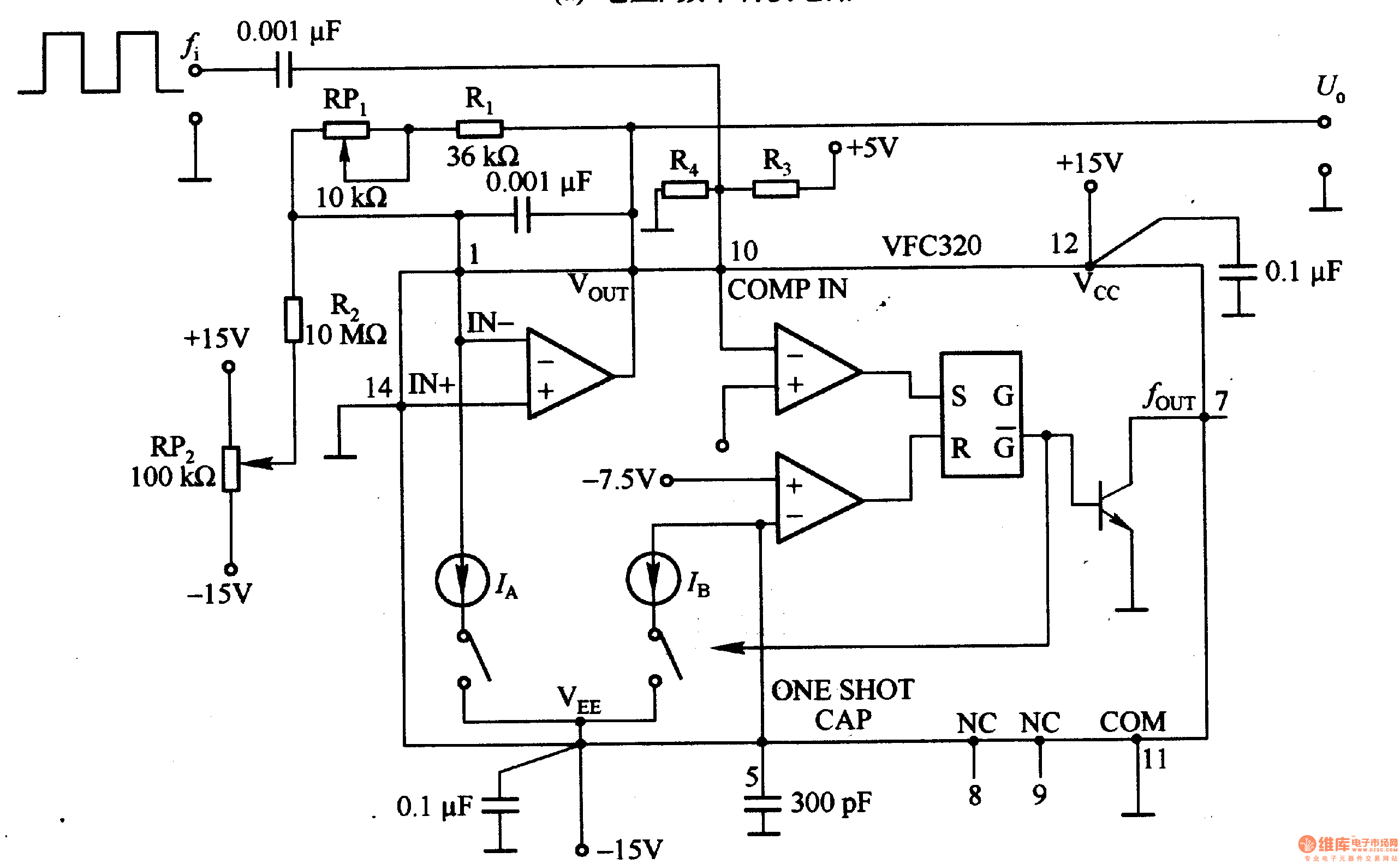
Description: Figure 1-22 (a) illustrates a circuit that converts an input voltage of 0 to +10V (Ui) into a pulse with an output frequency ranging from 0 to 100kHz. In this configuration, pin 7 of the VFC320 is connected to a resistor, allowing for direct interfacing with standard logic levels. Figure 1-22 (b) depicts a circuit designed to convert a pulse with an input frequency of 0 to 100kHz into an output voltage (Uo) that ranges from 0 to +10V.
The circuit in Figure 1-22 (a) utilizes a voltage-to-frequency converter (VFC), specifically the VFC320, which is designed to generate a frequency output proportional to the input voltage. The input voltage is applied to the VFC320, which modulates the output frequency based on the input signal. The output frequency can be adjusted by changing the values of the resistors and capacitors in the circuit. The connection of pin 7 to a resistor enables the output to interface seamlessly with standard digital logic circuits, allowing for further processing or control applications.
In Figure 1-22 (b), the circuit takes a pulse input with a frequency range of 0 to 100kHz and converts it back into a corresponding output voltage ranging from 0 to +10V. This conversion is typically achieved using a frequency-to-voltage converter (FVC), which processes the incoming pulse signal and generates a DC output voltage that is proportional to the frequency of the input pulse. The output voltage can be fine-tuned using additional components in the circuit, such as operational amplifiers or voltage dividers, to ensure compatibility with various applications that require a specific voltage range.
Overall, both circuits exemplify the versatility and functionality of voltage and frequency conversion in electronic applications, enabling seamless integration between analog and digital systems.Figure 1-22 (a) shows the circuit which could convert 0-+lOV input voltage Ui into the pulse with 0 -1OOkHz output frequency, and pin 7 of VFC320 is connected a resistor to directly connect to standard logic. Figure 1-22 (b) shows the the circuit which could convert the pulse with 0-100KHz input frequency into 0-+lOV output voltage UO.
If the signal counter..
The circuit in Figure 1-22 (a) utilizes a voltage-to-frequency converter (VFC), specifically the VFC320, which is designed to generate a frequency output proportional to the input voltage. The input voltage is applied to the VFC320, which modulates the output frequency based on the input signal. The output frequency can be adjusted by changing the values of the resistors and capacitors in the circuit. The connection of pin 7 to a resistor enables the output to interface seamlessly with standard digital logic circuits, allowing for further processing or control applications.
In Figure 1-22 (b), the circuit takes a pulse input with a frequency range of 0 to 100kHz and converts it back into a corresponding output voltage ranging from 0 to +10V. This conversion is typically achieved using a frequency-to-voltage converter (FVC), which processes the incoming pulse signal and generates a DC output voltage that is proportional to the frequency of the input pulse. The output voltage can be fine-tuned using additional components in the circuit, such as operational amplifiers or voltage dividers, to ensure compatibility with various applications that require a specific voltage range.
Overall, both circuits exemplify the versatility and functionality of voltage and frequency conversion in electronic applications, enabling seamless integration between analog and digital systems.Figure 1-22 (a) shows the circuit which could convert 0-+lOV input voltage Ui into the pulse with 0 -1OOkHz output frequency, and pin 7 of VFC320 is connected a resistor to directly connect to standard logic. Figure 1-22 (b) shows the the circuit which could convert the pulse with 0-100KHz input frequency into 0-+lOV output voltage UO.
If the signal counter..
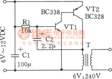
Pulse Signal Generator
The volt-ampere characteristics of a tunnel diode exhibit an S-shaped curve. The peak current point, referred to as point P, represents the maximum current, while the valley point, denoted as point V, indicates the minimum current. Key parameters of the...
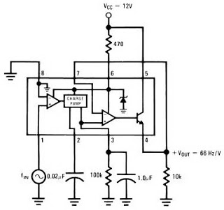
ic lm2917 frequency to voltage
The LM2917 IC chip is specifically designed as a Frequency to Voltage Converter. Its applications as a Frequency to Voltage Converter require few external components. The LM2917 datasheet includes several examples of its applications. The advantages of the single-chip LM2917...
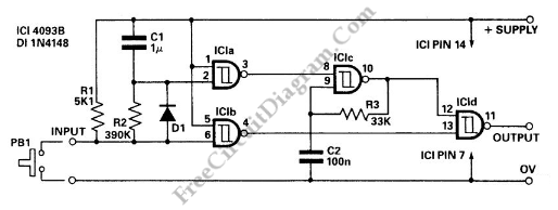
Pulse Delay Generator
This circuit is a delayed pulse generator that provides pulse rate and independent control of the initial delay. The pulse generator of this circuit is.
The delayed pulse generator circuit is designed to produce a pulse output after a specified delay,...
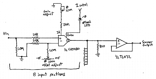
Interpolating Scanner Circuit
This design is for an interpolating scanner, a circuit featuring multiple signal inputs, a control voltage input, and a signal output. The output selectively transitions between inputs, smoothly fading from one to the next as the control voltage increases. A...
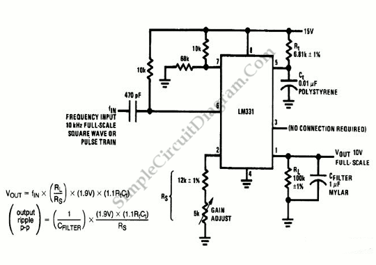
LM331 Frequency to Voltage Converter
The frequency-to-voltage converter circuit depicted in the schematic diagram produces a 10 V output for a 10 kHz full-scale input (square waves or pulses). The simplicity of the circuit does not compromise its performance, achieving a linearity of approximately 0.06%...
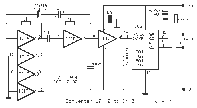
10MHZ to 1MHz converter
This circuit is an oscillator at frequency 10MHZ, using IC 1A and IC1B and a frequency divider. Using the IC2 it divides the pulses to 10. IC1C is a buffer. The variable capacitor 39pF is microtuning the frequency. The pin...
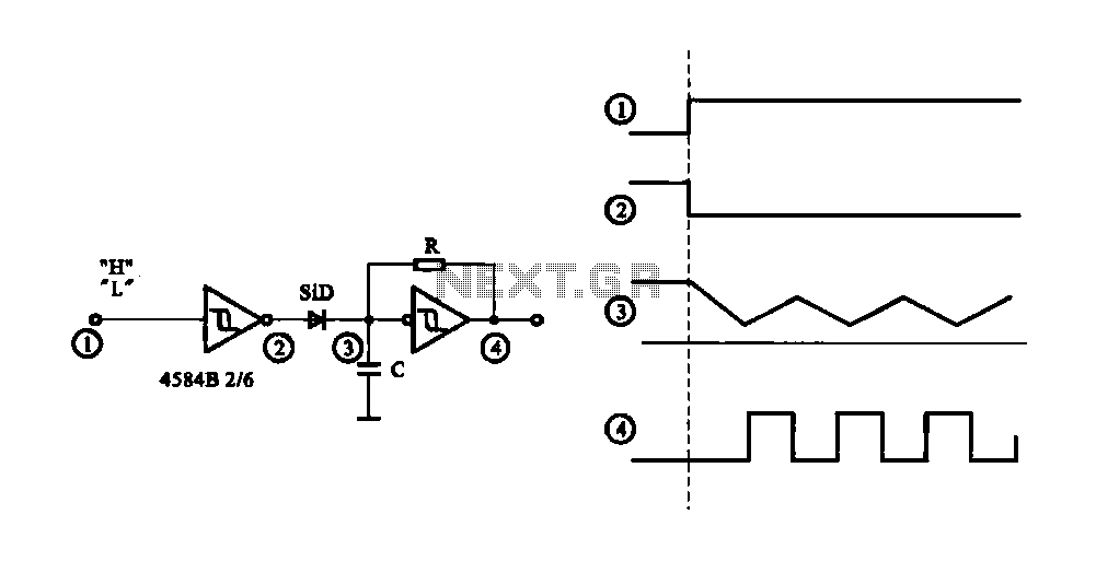
Controlled pulse signal generating circuit
The circuit generates a controlled pulse signal. When a high pulse signal is applied to the input terminal O (start), the output pulse signal is activated. Conversely, when a low signal is received at the input terminal O (stop), the...
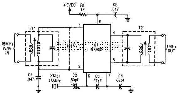
Simple Wwv Converter For Auto Radios Circuit
This simple frequency converter mixes the 15-MHz WWV/WVH signal with a 16-MHz signal from the local oscillator (LO) to convert it down to 1 MHz, enabling it to be received on an AM-band receiver.
The frequency converter operates by utilizing a...
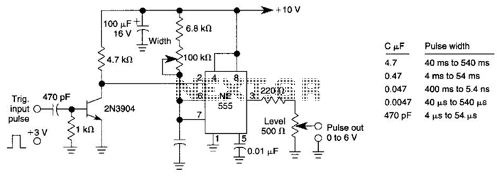
Add-On Pulse Generator Circuit
This pulse generator can enhance a standalone pulse generator. By utilizing a transistor and a 555 timer, it can produce pulse widths ranging from 5 microseconds to 500 microseconds. The value of capacitor C3 can be approximately determined using the...