
latching relay circuit
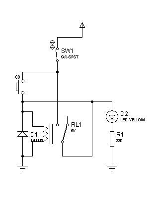
The described circuit utilizes a latching relay that can be activated by logic integrated circuits (ICs) such as TTL (Transistor-Transistor Logic) or CMOS (Complementary Metal-Oxide-Semiconductor) devices. The interfacing between these logic ICs and the latching relay requires careful consideration to ensure proper operation and voltage levels.
To facilitate this interfacing, a secondary relay is employed as a trigger mechanism. This relay acts as an intermediary that converts the low-level signals from the logic ICs into a higher current signal suitable for activating the latching relay. The choice of the secondary relay should be based on its ability to handle the voltage and current levels required by the latching relay while ensuring that the control signals from the logic ICs are adequately processed.
The circuit design typically includes a flyback diode connected in parallel with the relay coil to protect the logic ICs from voltage spikes generated when the relay is de-energized. Additionally, resistors may be used to limit the current flowing into the relay coil, ensuring that the logic ICs are not overloaded.
In summary, the operation of the latching relay circuit can be effectively controlled by TTL or CMOS logic ICs through the use of a secondary relay as a trigger mechanism, providing a reliable and efficient method for interfacing between digital logic and electromechanical components.The circuit can also be triggered by logic ICs(TTL/CMOS) using proper interfacing method. I usually use another relay that serve as the trigger button when interfacing ICs to latching relay circuit. 🔗 External reference
Related Circuits
A very popular circuit for driving DC motors (ordinary or gearhead) is called an H-bridge. It's called that because it looks like the capital letter 'H' on classic schematics. The great ability of an H-bridge circuit is that the...
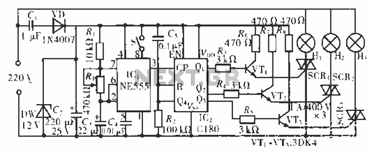
The circuit operates at 220 V AC using a C1 buck converter and a DW regulator. The VD ensures the entire stream is processed, and C2 provides a filtered output of 12 V DC for the voltage supply control...
Color sensing using a camera and a sufficiently powered processor that runs image histogram logic (or similar algorithms) can reliably determine the presence of specific colors. However, alternatives that are significantly more cost-effective for detecting the presence or absence...
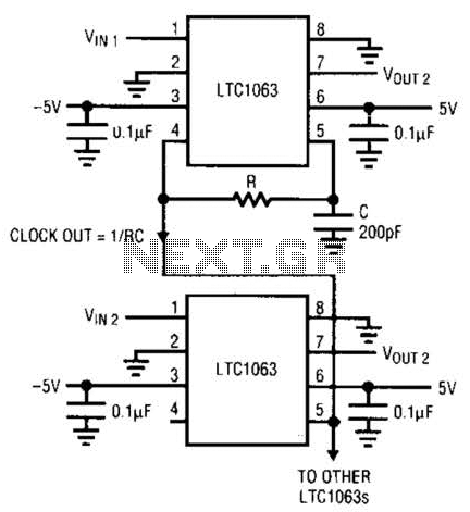
The LTC1063 is a monolithic low-pass filter that provides exceptional DC and AC performance. It features both internal and external clock tunability, with cutoff frequencies reaching up to 50 kHz, a typical output DC offset of 1 mV, and...
Channel Relay Board is a simple and convenient way to interface 8 relays for switching application in your project. Input - 12 VDC @ 336 mA. Output - eight SPDT relay. Relay specification - 5 A @ 230 VAC....
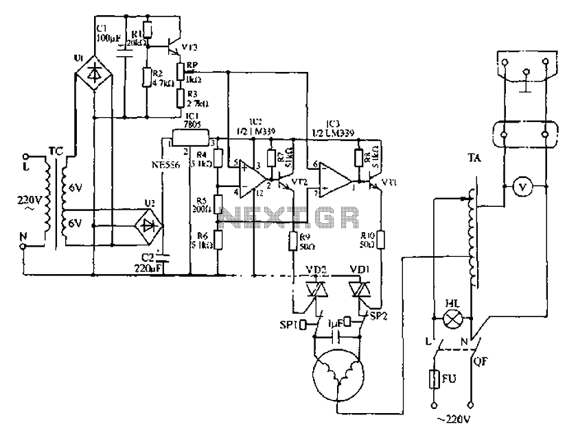
Automatic AC voltage regulator circuit The automatic AC voltage regulator circuit is designed to maintain a stable output voltage despite fluctuations in the input voltage. This circuit is essential for protecting sensitive electronic devices from voltage variations that can lead...