


12 Neon Lamps Sequencer circuit
#neon lamps
#sequencer
#high voltage
#switching power supply
#74HC14
#Schmitt trigger
#oscillator
#ni-cad cells
#PNP transistor
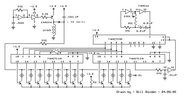
Description: This circuit is similar to the LED clock using 12 neon indicator lamps instead of LEDs. It operates from 2 high capacity ni-cad cells (2.5 volts) which keep it going for a couple weeks. High voltage (70 volts) for the neon lamps is obtained from a small switching power supply using a 74HC14 Schmitt trigger squarewave oscillator, high voltage switching transistor, and 10 mH high Q inductor. Most any small PNP transistors can be used that have a C/E voltage rating of 80 or more. The inverter stage (pins 5,6) is not needed and is just an extra stage. An adjustable low frequency oscillator made from two of the inverter stages generates the clock signal for the 74HCT393 binary counter. In this circuit, the timing capacitor should be non-polarized since the capacitor will charge in both directions, so two 6.8 uF tantalum caps were used back to back which yields about 3.3 uF. The 75K resistor in series with pin 1 limits the current through the input protection diodes when the capacitor voltage exceeds the supply voltage. This resistor may not be necessary with small capacitors at low voltage but was added as a precaution. The binary counts are decoded into 1 of 12 outputs by the 74HCT138 decoders and operates the same way as in the 28 LED clock circuit. The sequence can be extended to 16 by omitting the reset circuit and tying pins 2 and 13 of the counter to ground.
This circuit design utilizes a set of 12 neon indicator lamps to create a visual clock display, similar to traditional LED clock circuits. The power supply for the entire circuit is derived from two nickel-cadmium (Ni-Cad) cells, providing a total voltage of 2.5 volts, which is sufficient to maintain operation for an extended period, typically a couple of weeks.
For the neon lamps to function, a high voltage of approximately 70 volts is necessary. This voltage is generated by a compact switching power supply that incorporates a 74HC14 Schmitt trigger configured as a square wave oscillator. The oscillator's output drives a high voltage switching transistor, which in turn energizes a 10 mH high-Q inductor to step up the voltage to the required level for the neon lamps. A variety of small PNP transistors can be employed in this role, provided they possess a collector-emitter voltage rating of at least 80 volts.
The circuit also features an adjustable low-frequency oscillator constructed from two inverter stages of the 74HC14. This oscillator generates the clock signal that drives a 74HCT393 binary counter. A critical component of this design is the timing capacitor, which must be non-polarized due to the bidirectional charging nature of the circuit. For this purpose, two 6.8 µF tantalum capacitors are arranged back-to-back, resulting in an effective capacitance of approximately 3.3 µF.
To protect the input of the binary counter, a 75K ohm resistor is placed in series with pin 1. This resistor serves to limit the current flowing through the input protection diodes, particularly when the voltage across the capacitor exceeds the supply voltage. While this resistor may be deemed unnecessary for small capacitors operating at low voltages, it is included in the design as a precautionary measure.
The binary output of the 74HCT393 counter is decoded into one of twelve outputs using a 74HCT138 decoder, facilitating the control of the neon lamps in a manner analogous to the operation of a 28 LED clock circuit. Additionally, the design allows for an extension of the counting sequence to 16 outputs. This can be achieved by omitting the reset circuit and grounding pins 2 and 13 of the counter, thus enabling the use of additional outputs if desired.This circuit is similar to the LED clock using 12 neon indicator lamps instead of LEDs. It operates from 2 high capacity ni-cad cells (2.5 volts) which keep it going for a couple weeks. High voltage (70 volts) for the neon lamps is obtained from a small switching power supply using a 74HC14 Schmitt trigger squarewave oscillator, high voltage switching transistor, and 10 mH high Q inductor. Most any small PNP transistors can be used that have a C/E voltage rating of 80 or more. The inverter stage (pins 5,6) is not needed and is just an extra stage. An adjustable low frequency oscillator made from two of the inverter stages generates the clock signal for the 74HCT393 binary counter. In this circuit, the timing capacitor should be non-polarized since the capacitor will charge in both directions, so two 6.8 uF tantalum caps were used back to back which yields about 3.3 uF.
The 75K resistor in series with pin 1 limits the current through the input protection diodes when the capacitor voltage exceeds the supply voltage. This resistor may not be necessary with small capacitors at low voltage but was added as a precaution.
The binary counts are decoded into 1 of 12 outputs by the 74HCT138 decoders and operates the same way as in the 28 LED clock circuit. The sequence can be extended to 16 by omitting the reset circuit and tying pins 2 and 13 of the counter to ground.
This circuit design utilizes a set of 12 neon indicator lamps to create a visual clock display, similar to traditional LED clock circuits. The power supply for the entire circuit is derived from two nickel-cadmium (Ni-Cad) cells, providing a total voltage of 2.5 volts, which is sufficient to maintain operation for an extended period, typically a couple of weeks.
For the neon lamps to function, a high voltage of approximately 70 volts is necessary. This voltage is generated by a compact switching power supply that incorporates a 74HC14 Schmitt trigger configured as a square wave oscillator. The oscillator's output drives a high voltage switching transistor, which in turn energizes a 10 mH high-Q inductor to step up the voltage to the required level for the neon lamps. A variety of small PNP transistors can be employed in this role, provided they possess a collector-emitter voltage rating of at least 80 volts.
The circuit also features an adjustable low-frequency oscillator constructed from two inverter stages of the 74HC14. This oscillator generates the clock signal that drives a 74HCT393 binary counter. A critical component of this design is the timing capacitor, which must be non-polarized due to the bidirectional charging nature of the circuit. For this purpose, two 6.8 µF tantalum capacitors are arranged back-to-back, resulting in an effective capacitance of approximately 3.3 µF.
To protect the input of the binary counter, a 75K ohm resistor is placed in series with pin 1. This resistor serves to limit the current flowing through the input protection diodes, particularly when the voltage across the capacitor exceeds the supply voltage. While this resistor may be deemed unnecessary for small capacitors operating at low voltages, it is included in the design as a precautionary measure.
The binary output of the 74HCT393 counter is decoded into one of twelve outputs using a 74HCT138 decoder, facilitating the control of the neon lamps in a manner analogous to the operation of a 28 LED clock circuit. Additionally, the design allows for an extension of the counting sequence to 16 outputs. This can be achieved by omitting the reset circuit and grounding pins 2 and 13 of the counter, thus enabling the use of additional outputs if desired.This circuit is similar to the LED clock using 12 neon indicator lamps instead of LEDs. It operates from 2 high capacity ni-cad cells (2.5 volts) which keep it going for a couple weeks. High voltage (70 volts) for the neon lamps is obtained from a small switching power supply using a 74HC14 Schmitt trigger squarewave oscillator, high voltage switching transistor, and 10 mH high Q inductor. Most any small PNP transistors can be used that have a C/E voltage rating of 80 or more. The inverter stage (pins 5,6) is not needed and is just an extra stage. An adjustable low frequency oscillator made from two of the inverter stages generates the clock signal for the 74HCT393 binary counter. In this circuit, the timing capacitor should be non-polarized since the capacitor will charge in both directions, so two 6.8 uF tantalum caps were used back to back which yields about 3.3 uF.
The 75K resistor in series with pin 1 limits the current through the input protection diodes when the capacitor voltage exceeds the supply voltage. This resistor may not be necessary with small capacitors at low voltage but was added as a precaution.
The binary counts are decoded into 1 of 12 outputs by the 74HCT138 decoders and operates the same way as in the 28 LED clock circuit. The sequence can be extended to 16 by omitting the reset circuit and tying pins 2 and 13 of the counter to ground.
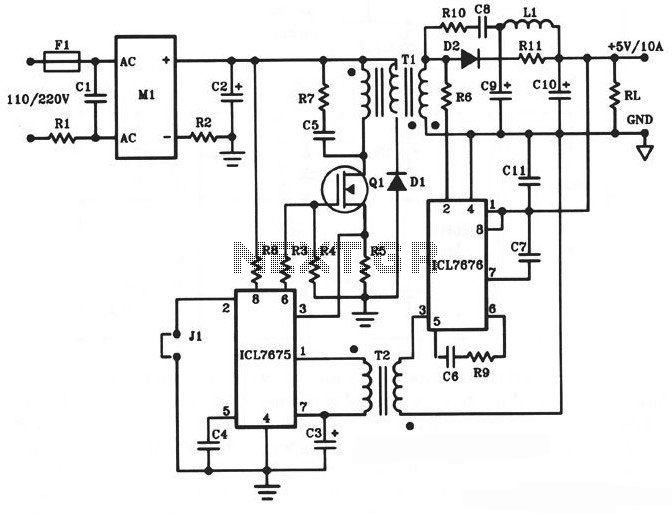
5V/10A 50W Offline Switching Power Supply
The following diagram illustrates a 50W offline switching power supply circuit design. This circuit is powered by a MOSFET, specifically the BUZ80A/IXTP4N8 for a 220V AC voltage input and the GE IRF823 for a 110V AC voltage input. The output...
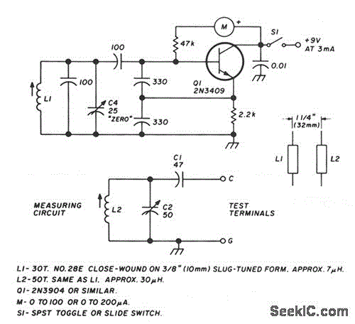
LC CHECKER
The circuit operates on the principle of the grid-dip or absorption effect, which takes place when a parallel resonant circuit is coupled to an oscillator operating at the same frequency. Transistor Q1 functions within a standard Colpitts oscillator circuit, maintaining...
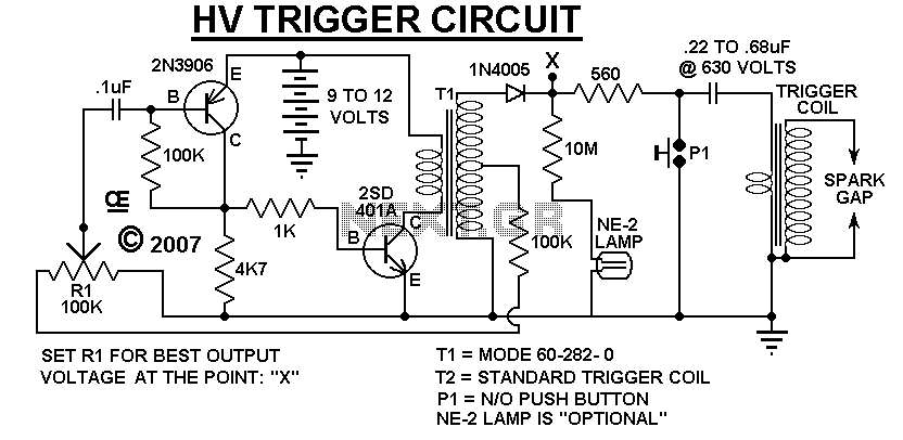
5000 Volts arc supply
A Very Low Current, High Voltage Spark, that is Manually Triggered. Although its not easily Measured, the Peak Output voltage will be over 5,000 Volts. T1 is a small audio transformer and it steps up the voltage to about 500...
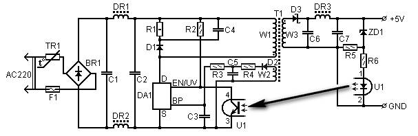
5 volt1 5a switching power supply based tny264p
5 Volt/1.5A Switching Power Supply based on the TNY264P power supply. Refer to the designated page for an explanation of the related circuit diagram.
The 5 Volt, 1.5A switching power supply utilizing the TNY264P is a compact and efficient power conversion...
Salvaging Interesting Gadgets Components and Subsystems
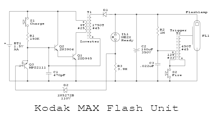
The high voltage power supply is likely capable of delivering between 12 to 30 kVDC at a current of 1 or 2 mA. This output is suitable for various high voltage applications, including experiments, plasma globes, negative ion and ozone...
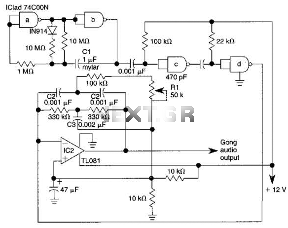
Electronic Gong Circuit
The electronic gong consists of an oscillator utilizing half of a 74C00 quad 2-input NAND gate, an active twin-T filter based on a TL081 operational amplifier, and an audio amplifier integrated circuit, such as the LM386N. Pulses generated by an...
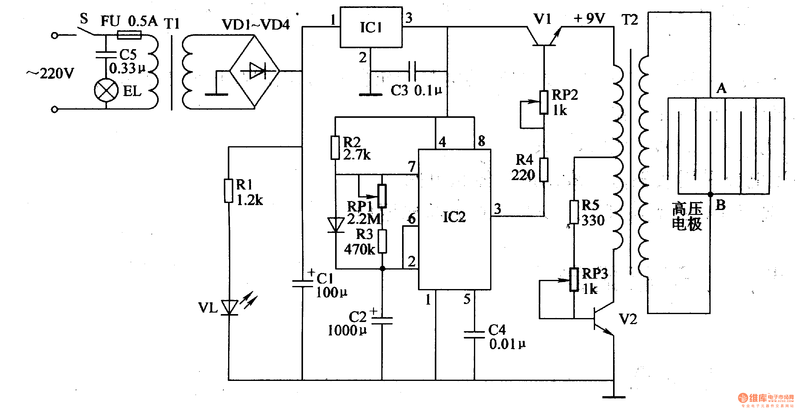
Electronic Pest Killing Lamp
Working Principle: The circuit, as illustrated in figure 4-187, is composed of three main components: the power circuit, the pulse oscillator, and the high voltage generator. The power circuit includes components S, FU, TI, VD1-VD4, C1, C3, IC1, R1, and...
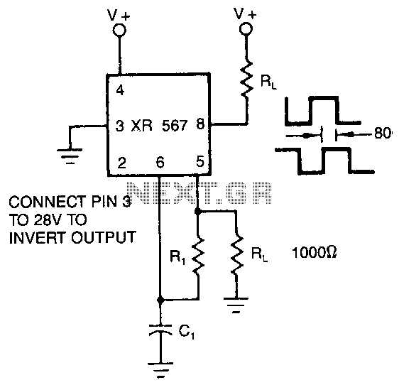
Quadrature-outputs-oscillator
The XR-567 operates as a precision oscillator, providing two distinct square-wave outputs at pins 5 and 8, which are nearly in quadrature phase with one another. Due to the internal biasing configuration, the typical phase shift between the two outputs...
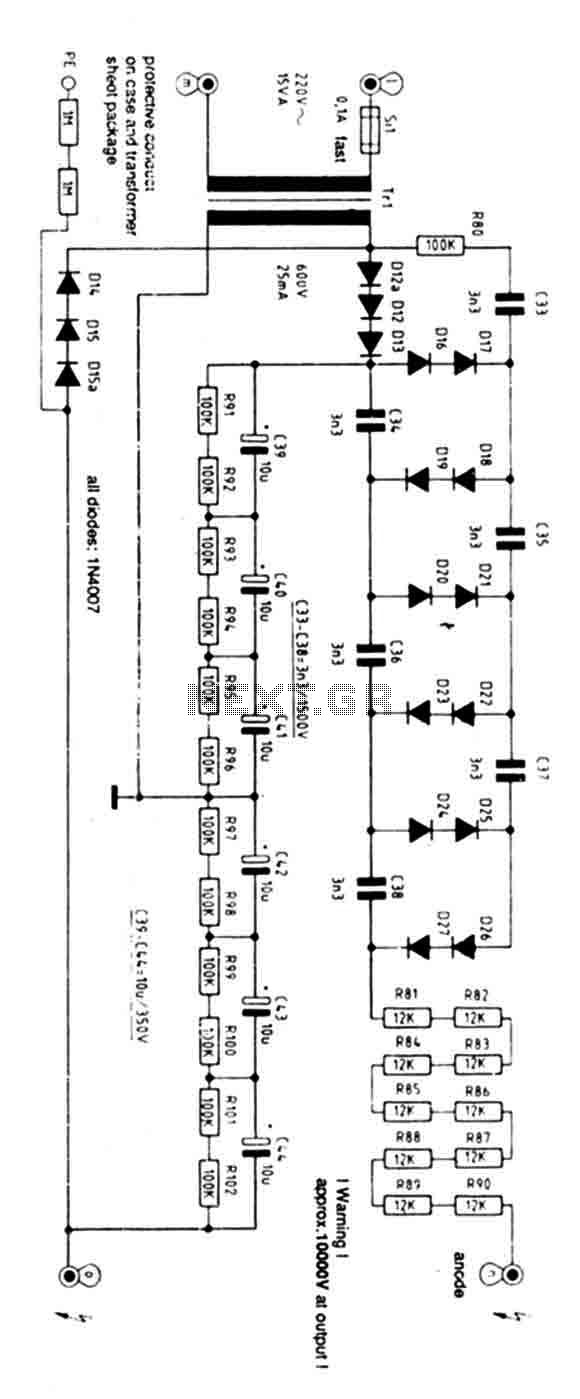
High Voltage Power Supply 10kV
Exercise caution with this power supply as it operates on 220V mains and has an output voltage of 10KV. Characteristics: Supply: 220V AC 50Hz mains, Power: 15 Watts, Ignition Voltage: 8KV.
The power supply operates on a standard 220V AC input...