


12 stage neon sequencer ne 2 ne 51
#neon lamps
#sequencer
#74HC14
#Schmitt trigger
#high voltage
#switching power supply
#oscillator
#ni-cad cells
#indicator lamps
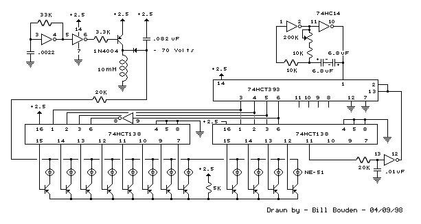
Description: This circuit resembles an LED clock, utilizing 12 neon indicator lamps in place of LEDs. It operates on two high-capacity nickel-cadmium (Ni-Cad) cells providing 2.5 volts, allowing sustained operation for several weeks. The high voltage (70 volts) required for the neon lamps is generated by a compact switching power supply, which employs a 74HC14 Schmitt trigger square wave oscillator, a high-voltage switching transistor, and a 10 mH high-Q inductor.
This circuit design features a unique approach to displaying time using neon lamps, which are known for their bright illumination and distinctive glow. The use of two Ni-Cad cells ensures that the circuit remains powered for an extended period, making it suitable for applications where frequent battery changes are impractical. The 74HC14 Schmitt trigger serves as the oscillator, generating a square wave signal that is essential for driving the switching transistor.
The high-voltage switching transistor is crucial for stepping up the voltage from the low-level input provided by the Ni-Cad cells. This transistor operates in a switching mode, allowing it to efficiently control the flow of current to the inductor. The inductor, rated at 10 mH and characterized by its high quality (high-Q), plays a vital role in the boost converter circuit by storing energy and releasing it at a higher voltage.
When the circuit is powered, the oscillator generates a square wave that alternates the state of the switching transistor. This rapid switching action causes the inductor to charge and discharge, ultimately generating the required 70 volts to illuminate the neon lamps. The design ensures that the neon indicators light up sequentially or in a pattern that can represent time, similar to a traditional clock.
Overall, this circuit combines efficient power management with innovative display technology, making it a practical solution for low-power, long-lasting timekeeping applications. The careful selection of components and their configuration is essential for achieving the desired performance and reliability in the operation of the neon lamp clock.This circuit is similar to the LED clock using 12 neon indicator lamps instead of LEDs. It operates from 2 high capacity ni-cad cells (2.5 volts) which keep it going for a couple weeks. High voltage (70 volts) for the neon lamps is obtained from a small switching power supply using a 74HC14 Schmitt trigger squarewave oscillator, high voltage switching transistor, and 10 mH high Q inductor..
This circuit design features a unique approach to displaying time using neon lamps, which are known for their bright illumination and distinctive glow. The use of two Ni-Cad cells ensures that the circuit remains powered for an extended period, making it suitable for applications where frequent battery changes are impractical. The 74HC14 Schmitt trigger serves as the oscillator, generating a square wave signal that is essential for driving the switching transistor.
The high-voltage switching transistor is crucial for stepping up the voltage from the low-level input provided by the Ni-Cad cells. This transistor operates in a switching mode, allowing it to efficiently control the flow of current to the inductor. The inductor, rated at 10 mH and characterized by its high quality (high-Q), plays a vital role in the boost converter circuit by storing energy and releasing it at a higher voltage.
When the circuit is powered, the oscillator generates a square wave that alternates the state of the switching transistor. This rapid switching action causes the inductor to charge and discharge, ultimately generating the required 70 volts to illuminate the neon lamps. The design ensures that the neon indicators light up sequentially or in a pattern that can represent time, similar to a traditional clock.
Overall, this circuit combines efficient power management with innovative display technology, making it a practical solution for low-power, long-lasting timekeeping applications. The careful selection of components and their configuration is essential for achieving the desired performance and reliability in the operation of the neon lamp clock.This circuit is similar to the LED clock using 12 neon indicator lamps instead of LEDs. It operates from 2 high capacity ni-cad cells (2.5 volts) which keep it going for a couple weeks. High voltage (70 volts) for the neon lamps is obtained from a small switching power supply using a 74HC14 Schmitt trigger squarewave oscillator, high voltage switching transistor, and 10 mH high Q inductor..
Salvaging Interesting Gadgets Components and Subsystems
The high voltage power supply is likely capable of delivering between 12 to 30 kVDC at a current of 1 or 2 mA. This output is suitable for various high voltage applications, including experiments, plasma globes, negative ion and ozone...
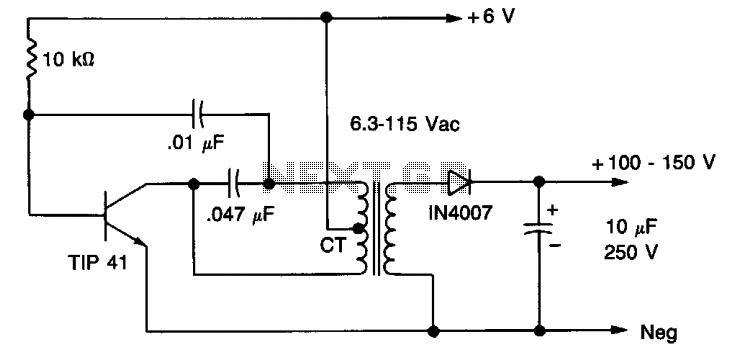
High voltage supply
A 6 V battery can provide 100-150 Vdc center-tapped at a high internal impedance (not dangerous though it can inflict an unpleasant jolt). A 6.3 V transformer is connected in reverse with a transistor used in a Hartley oscillator configuration....
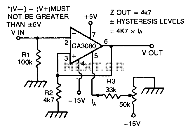
Schmitt trigger with programmable hysteresis
The CA 3088 is utilized as a versatile Schmitt trigger. The magnitude of the hysteresis levels is determined by the current (Ia) flowing out of the amplifier's output and through resistor R2. An increase in Ia results in an increase...
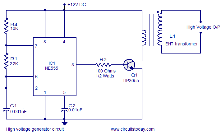
High voltage generator circuit
This circuit is highly dangerous due to its output voltage, which is in kilovolts and poses a significant risk of serious injury or death. It should only be attempted by individuals with extensive experience in handling high voltages. No responsibility...
0 1000 volt regulated high voltage
The input voltage for the high-voltage DC-DC converter is 12V AC at 800mA, which is then converted to DC using a 1A bridge rectifier diode. The output voltage of the converter can be adjusted within the range of 0-1000V DC....
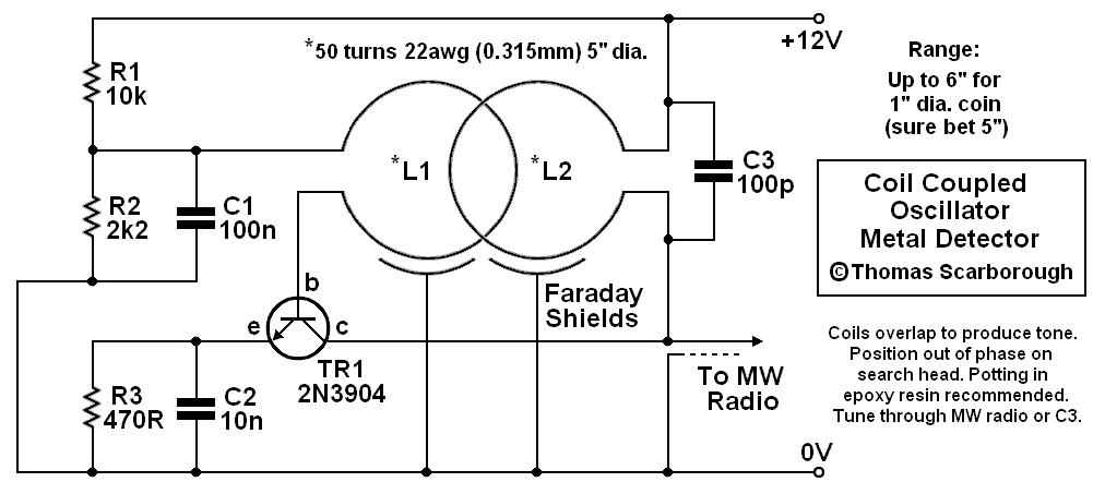
coil coupled operation metal
The metal detector presented may represent a new category in its field. After some exposure, it has been recognized as such by those familiar with it. This device is based on a standard transformer coupled oscillator (TCO), which is why...
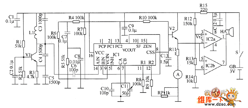
Metal detector circuit diagram 8
The metal detector circuit consists of a probe oscillator, a PLL (phase-locked loop) circuit, and an audio alarm circuit. The probe oscillator includes a detection coil (L), transistor (V1), and several resistors (R1 to R3) and capacitors (C1 to C5)....
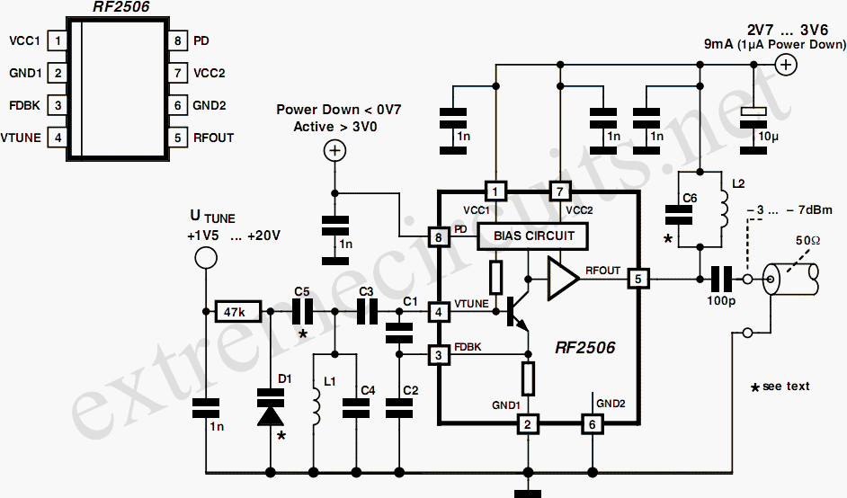
10 to 1000 MHz Oscillator circuit with RF2506
Today, it is no longer necessary to use discrete components for constructing oscillators. Many manufacturers now offer ready-made voltage-controlled oscillator (VCO) integrated circuits (ICs) that require only a few external components to determine the frequency. An example of such an...
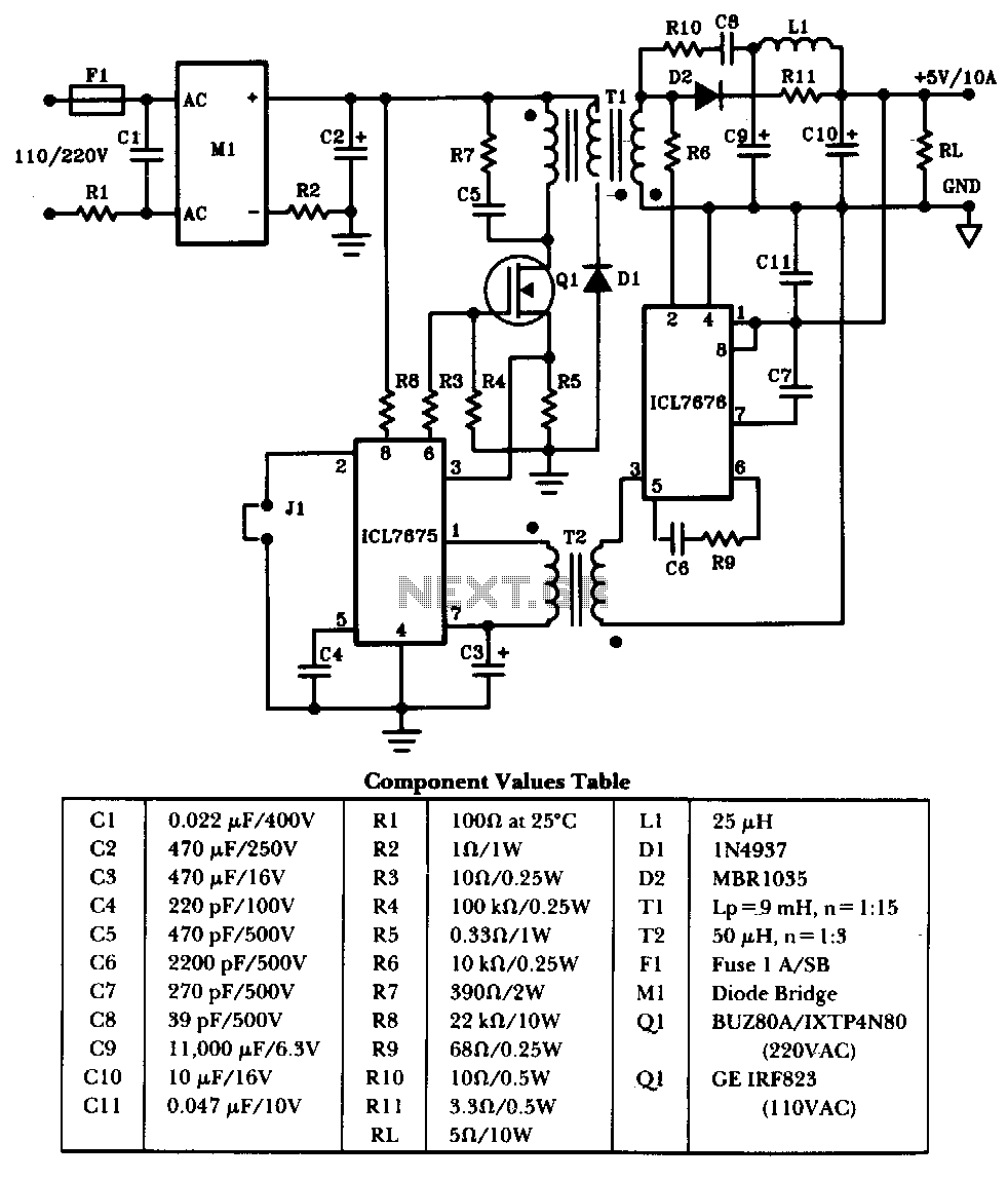
50W-offline-switching-power-supply
The schematic illustrates a 50W power supply providing a 5V, 10A output. It operates as a flyback converter in continuous mode. The circuit incorporates both primary and secondary side controllers, offering full protection against fault conditions such as overcurrent. Once...