


120VAC Lamp Chaser circuit
#lamp chaser
#AC lamps
#solid state relays
#LED sequencer
#120VAC
#relay control
#light control
#circuit design
#electronics
#home automation
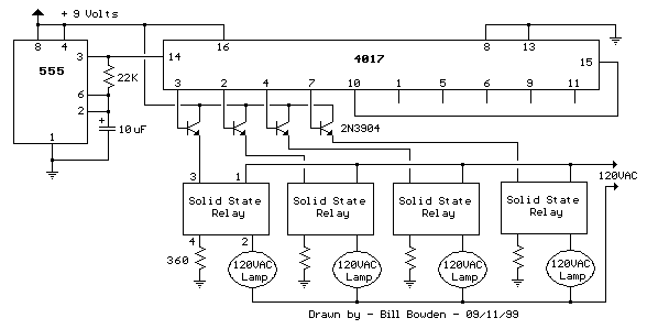
Description: This circuit is fundamentally similar to the channel LED sequencer, with the enhancement of solid-state relays for controlling AC lamps. The relay depicted in the diagram is a Radio Shack 3 amp unit (part no. 275-310), which requires 1.2 volts DC for activation. Although no current specification is provided, it is assumed that only a few milliamps are necessary to illuminate the internal LED. A 360-ohm resistor is included, which limits the current to 17 mA when using a 9-volt supply.
The circuit operates by utilizing the solid-state relay to switch AC lamps on and off in synchronization with a sequence determined by the LED indicators. The relay's low activation voltage (1.2 volts DC) makes it suitable for integration with various low-voltage control circuits, ensuring compatibility with microcontrollers or other logic devices that can output this voltage level.
When designing the circuit, the 360-ohm resistor plays a critical role in limiting the current flowing through the relay's activation circuit. Given a 9-volt supply, Ohm's law (V = IR) dictates that the maximum current through the resistor can be calculated as follows:
I = V/R = 9V / 360Ω ≈ 0.025A or 25mA.
This current is well within the operational limits for most low-power control applications. However, it is essential to confirm that the relay's internal LED can operate effectively with this current level, ensuring reliable performance without risk of damage.
The solid-state relay itself is designed to handle up to 3 amps of AC current, making it suitable for controlling standard household lamps or other light fixtures. The use of solid-state components provides advantages over traditional electromechanical relays, including faster switching times, longer operational life, and reduced electromagnetic interference.
In summary, this circuit effectively combines the functionality of an LED sequencer with the robust capabilities of solid-state relays, providing a reliable method for controlling AC lamps in a sequenced manner. Careful consideration should be given to component ratings and specifications to ensure optimal performance and safety in the final application.This circuit is basically the same as the channel LED sequencer with the addition of solid state relays to control the AC lamps. The relay shown in the diagram is a Radio Shack 3 amp unit (part no. 275-310) that requires 1.2 volts DC to activate. No current spec was given but I assume it needs just a few milliamps to light the internal LED. A 360 ohm resistor is shown which would limit the current to 17 mA using a 9 volt supply..
The circuit operates by utilizing the solid-state relay to switch AC lamps on and off in synchronization with a sequence determined by the LED indicators. The relay's low activation voltage (1.2 volts DC) makes it suitable for integration with various low-voltage control circuits, ensuring compatibility with microcontrollers or other logic devices that can output this voltage level.
When designing the circuit, the 360-ohm resistor plays a critical role in limiting the current flowing through the relay's activation circuit. Given a 9-volt supply, Ohm's law (V = IR) dictates that the maximum current through the resistor can be calculated as follows:
I = V/R = 9V / 360Ω ≈ 0.025A or 25mA.
This current is well within the operational limits for most low-power control applications. However, it is essential to confirm that the relay's internal LED can operate effectively with this current level, ensuring reliable performance without risk of damage.
The solid-state relay itself is designed to handle up to 3 amps of AC current, making it suitable for controlling standard household lamps or other light fixtures. The use of solid-state components provides advantages over traditional electromechanical relays, including faster switching times, longer operational life, and reduced electromagnetic interference.
In summary, this circuit effectively combines the functionality of an LED sequencer with the robust capabilities of solid-state relays, providing a reliable method for controlling AC lamps in a sequenced manner. Careful consideration should be given to component ratings and specifications to ensure optimal performance and safety in the final application.This circuit is basically the same as the channel LED sequencer with the addition of solid state relays to control the AC lamps. The relay shown in the diagram is a Radio Shack 3 amp unit (part no. 275-310) that requires 1.2 volts DC to activate. No current spec was given but I assume it needs just a few milliamps to light the internal LED. A 360 ohm resistor is shown which would limit the current to 17 mA using a 9 volt supply..
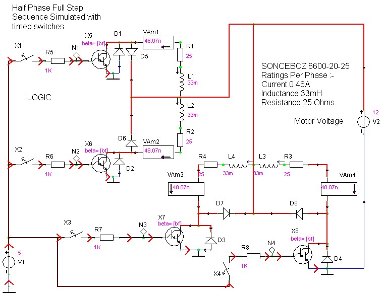
case stepper
Beige Bag Software has been offering affordable and innovative circuit design tools since 1990. B2 Spice provides schematics as well as analog, digital, and mixed-mode electronic circuit simulation. It integrates with EAGLE and CADSTAR PCB software.
B2 Spice is a powerful...
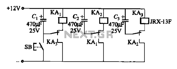
Alternately flashing one of a plurality of sets of high-power lights a chain circuit
The relay control allows for multiple pairs of contacts to be connected in parallel, enabling the circuit to handle a large lamp power. The design is straightforward; by simply changing the capacitance of the capacitor, different flash frequencies can be...
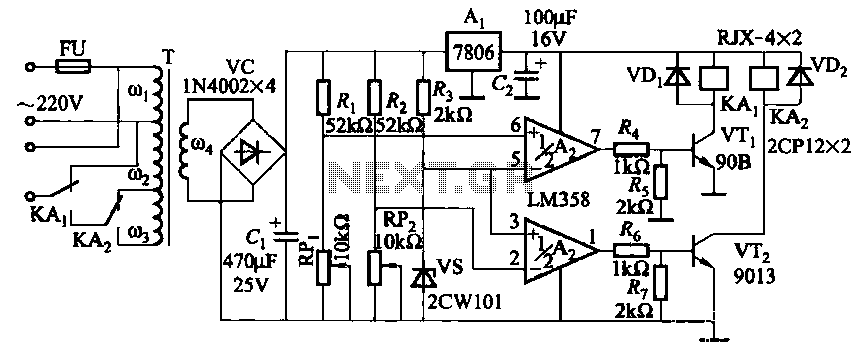
Relay control auto-transformer AC power supply circuit
It utilizes two LM358 operational amplifiers, A2 and Ar, to create a voltage measurement comparison control circuit for upper and lower limit voltage settings. The circuit includes a Raspberry Pi adjustment potentiometer (RPi) and an additional potentiometer (RP2) to modify...
automatic room light controller with
The objective of this project is to create a controller-based model that counts the number of individuals entering a specific room and activates the lighting accordingly. A sensor will be utilized to determine the current number of persons present. In...
Automatic light control circuit curtains
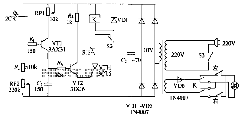
The circuit operates as follows: each morning, light enters the silicon photocell, generating a force that causes transistor VT1 to conduct. As a result, capacitor C charges, leading to an increase in voltage. This rising voltage causes the emitter current...
18 stage led sequencer
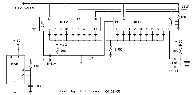
When power is applied, the 15K resistor and 10µF capacitor at pin 15 will reset the counters to a zero count, with pin 3 at +12V and all other outputs at zero. The two diodes (1N914) and a 15Ω resistor...
18 LED sequencer timer
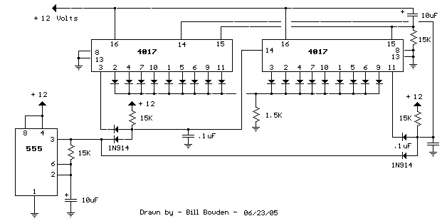
The question sometimes comes up of how to cascade 4017 decade counters for more than 10 sequential stages. The LED sequencer below shows a possible solution using a few extra parts. When power is applied, the 15K resistor and 10uF...
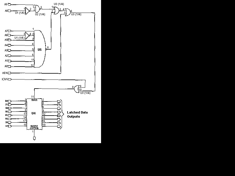
Computerize Your Room/House
You have read about computerized rooms or seen home automation products advertised in electronics magazines. You have decided to try it yourself. However, it is important to note that this project is not inexpensive. A computer is required, which is...
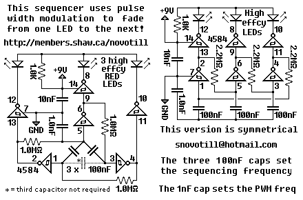
Strange LED sequencer
This deceptively simple sequencer actually pulse width modulates the LEDs as it fades from one LED to the next. Bulbs will last much longer when driven in this gentle manner. Add MOSFETs or transistors to the outputs if you wish...