


16 stage bi directional led sequencer
#LED sequencer
#CD4516
#74HC138
#Schmitt Trigger
#binary counter
#Night Rider display
#bidirectional
#decoder
#oscillator
#adjustable rate
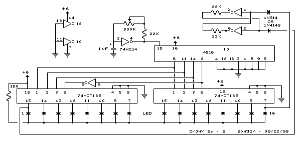
Description: The bi-directional sequencer employs a 4-bit binary up/down counter (CD4516) along with two "1 of 8 line decoders" (74HC138 or 74HCT138) to create the well-known "Night Rider" display. A Schmitt Trigger oscillator generates the clock signal for the counter, and the rate can be modified using a 500K potentiometer.
The bi-directional sequencer circuit is designed to produce a visual effect similar to the "Night Rider" display, characterized by a moving light pattern. The core of the circuit is the CD4516, a 4-bit binary up/down counter that counts in both directions based on control inputs. This counter can be configured to count up or down depending on the logic levels applied to its control pins.
The output from the CD4516 is fed into two 1 of 8 line decoders, such as the 74HC138 or 74HCT138. These decoders take the 3-bit output from the counter and activate one of eight output lines, allowing for the sequential lighting of LEDs or other indicators in a specific pattern. The use of two decoders ensures that the circuit can handle the full range of outputs from the counter, providing a smooth transition between states.
A Schmitt Trigger oscillator is incorporated into the design to provide a stable clock signal to the CD4516. This oscillator generates a square wave signal, which is essential for synchronizing the counting process. The frequency of the clock signal can be adjusted via a 500K potentiometer, allowing the user to change the speed of the light sequence. By varying the resistance, the duty cycle and frequency of the oscillator can be fine-tuned, resulting in a customizable visual effect.
Overall, this bi-directional sequencer circuit is an excellent example of digital electronics in action, combining counters, decoders, and oscillators to create a dynamic display that can be used in various applications, from decorative lighting to educational demonstrations in digital logic.The bi-directional sequencer uses a 4 bit binary up/down counter (CD4516) and two ""1 of 8 line decoders"" (74HC138 or 74HCT138) to generate the popular ""Night Rider"" display. A Schmitt Trigger oscillator provides the clock signal for the counter and the rate can be adjusted with the 500K pot..
The bi-directional sequencer circuit is designed to produce a visual effect similar to the "Night Rider" display, characterized by a moving light pattern. The core of the circuit is the CD4516, a 4-bit binary up/down counter that counts in both directions based on control inputs. This counter can be configured to count up or down depending on the logic levels applied to its control pins.
The output from the CD4516 is fed into two 1 of 8 line decoders, such as the 74HC138 or 74HCT138. These decoders take the 3-bit output from the counter and activate one of eight output lines, allowing for the sequential lighting of LEDs or other indicators in a specific pattern. The use of two decoders ensures that the circuit can handle the full range of outputs from the counter, providing a smooth transition between states.
A Schmitt Trigger oscillator is incorporated into the design to provide a stable clock signal to the CD4516. This oscillator generates a square wave signal, which is essential for synchronizing the counting process. The frequency of the clock signal can be adjusted via a 500K potentiometer, allowing the user to change the speed of the light sequence. By varying the resistance, the duty cycle and frequency of the oscillator can be fine-tuned, resulting in a customizable visual effect.
Overall, this bi-directional sequencer circuit is an excellent example of digital electronics in action, combining counters, decoders, and oscillators to create a dynamic display that can be used in various applications, from decorative lighting to educational demonstrations in digital logic.The bi-directional sequencer uses a 4 bit binary up/down counter (CD4516) and two ""1 of 8 line decoders"" (74HC138 or 74HCT138) to generate the popular ""Night Rider"" display. A Schmitt Trigger oscillator provides the clock signal for the counter and the rate can be adjusted with the 500K pot..
Microcontroller Clocking a Transmitter?
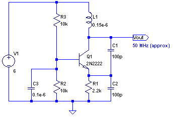
The core of any transmitter is typically an oscillator circuit, and in simple transmitters, such as QRSS devices, a crystal is often used. Frequency adjustment is achieved by modifying the capacitance to ground on one of the crystal's legs. Simple...
Schmitt Trigger Circuit
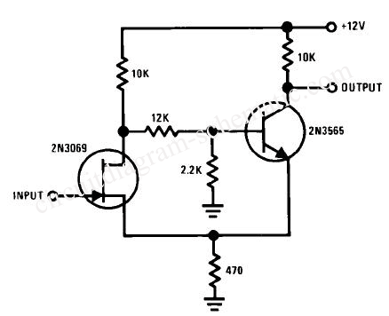
This Schmitt trigger circuit is emitter coupled and provides a simple comparator action. The 2N3069 JFET places very little loading on the measured input. Schmitt trigger, emitter coupled, simple comparator, 2N3565, distinct hysteresis loop.
The described circuit utilizes an emitter-coupled Schmitt...
Wireless keyboard circuit
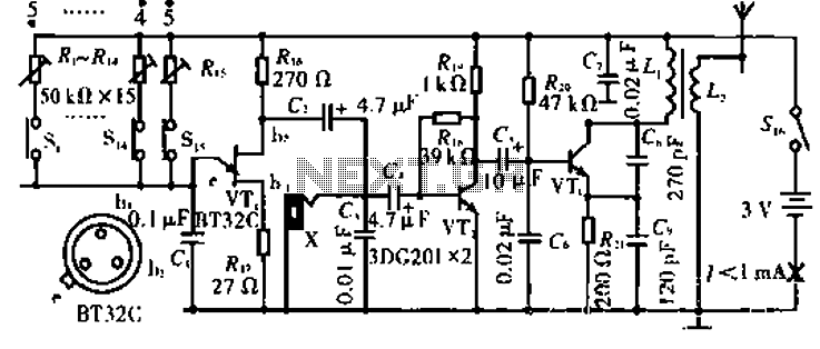
The circuit operates with VT3 and associated components arranged as a common-base capacitance feedback oscillation circuit. The oscillation frequency is set by capacitors C8, C9, and inductor L1. VT2 serves as a voltage amplification stage that reinjects the audio signal...

Oscillator-clock generator
This self-starting fixed frequency oscillator circuit provides excellent frequency stability. R1 and C1 form the frequency-determining network, while R2 supplies regenerative feedback. Diode D1 improves stability by compensating for the difference between Voh and Vsupply. In applications requiring a precision...
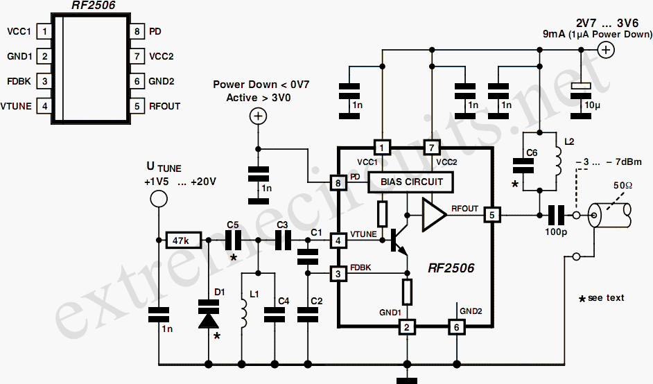
10 to 1000 MHz Oscillator circuit with RF2506
Today, it is no longer necessary to use discrete components for constructing oscillators. Many manufacturers now offer ready-made voltage-controlled oscillator (VCO) integrated circuits (ICs) that require only a few external components to determine the frequency. An example of such an...
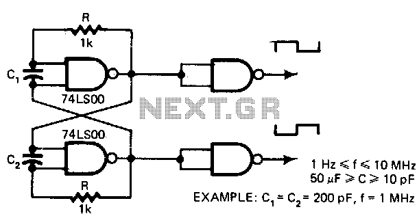
5-V-oscillator
This low-cost oscillator is consistently self-starting and capable of operating from over 1 Hz to 10 MHz, requiring only five components. The period of oscillation can be calculated using the relationship: P = 5 x 10^3 C seconds when C...
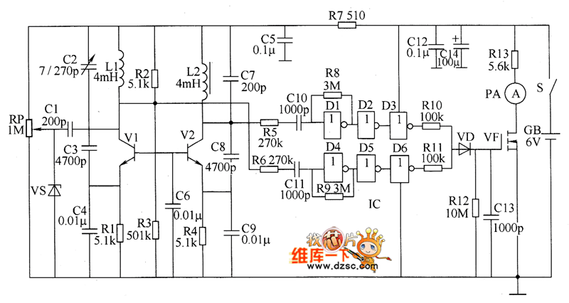
Metal detector circuit diagram 6
The metal detector circuit consists of several key components including the probe oscillator, reference oscillator, oscillation signal processor, mixing amplifier, and ammeter PA. The probe oscillator is made up of the oscillating tube VI, exploration coil L1, capacitors C1 to...
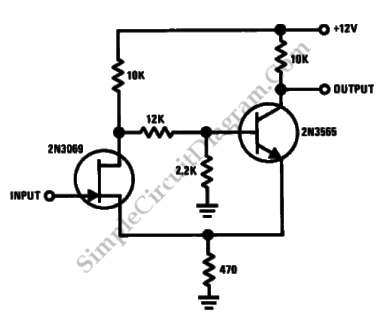
Discrete Schmitt Trigger
This is a Schmitt trigger circuit. This circuit produces a simple comparator action. It is emitter-coupled. This circuit has a distinct hysteresis loop.
The Schmitt trigger circuit is a fundamental electronic component utilized for signal conditioning, providing a means to convert...
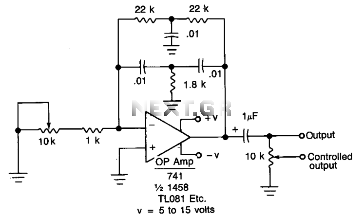
Oscillator IIV
When the oscillator is connected to a DC circuit, a DC blocking capacitor should be connected in series with the potentiometer's wiper arm. For finer output control, a 10 kΩ potentiometer can be added.
In this circuit configuration, the oscillator generates...