


16 Stage Bi-Directional LED Sequencer circuit
#LED sequencer
#CD4516
#74HC138
#Schmitt Trigger
#binary counter
#up/down counter
#Night Rider display
#oscillator
#potentiometer
#decoder
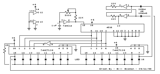
Description: The bi-directional sequencer employs a 4-bit binary up/down counter (CD4516) and two "1 of 8 line decoders" (74HC138 or 74HCT138) to create the well-known "Night Rider" display. A Schmitt Trigger oscillator generates the clock signal for the counter, with the rate adjustable via a 500K potentiometer. Additionally, two Schmitt Trigger inverters are utilized as an ET/RESET latch to manage the counting direction (up or down). It is crucial to use the 74HC14 instead of the 74HCT14, as the latter may not function correctly due to its low TTL input trigger level. When the maximum count (1111) is reached, the low output at pin 7 sets the latch, causing the UP/DOWN input to the counter to go low and initiate decrementing. Conversely, when the minimum count (0000) is reached, the latch is reset (high), allowing the counter to increment on the next rising clock edge. The three lowest counter bits (Q0, Q1, Q2) are connected in parallel to both decoders, while the highest bit (Q3) selects the appropriate decoder. This circuit can also drive 12-volt/25-watt lamps by adding two transistors per lamp, as detailed in the section titled "Interfacing 5 volt CMOS to 12 volt loads."
The bi-directional sequencer circuit is designed to produce a visually appealing LED display, reminiscent of the "Knight Rider" effect, where lights sequentially illuminate in a back-and-forth motion. The core of this circuit is the CD4516, a 4-bit binary up/down counter that can count both upwards and downwards based on the control signals provided. The counting direction is determined by the ET/RESET latch, which is implemented using Schmitt Trigger inverters (74HC14). This choice of components is essential as the 74HC14 has a higher input trigger level, ensuring reliable operation in CMOS applications.
The clock signal that drives the counter is generated by a Schmitt Trigger oscillator, which provides a stable and adjustable frequency. The inclusion of a 500K potentiometer allows for fine-tuning of the oscillation rate, enabling the user to customize the speed of the LED sequence. The output of the counter is fed into two 1 of 8 line decoders (74HC138 or 74HCT138), which interpret the binary count and activate the corresponding output lines, driving the LED display.
The design includes a mechanism to reverse the counting direction upon reaching the maximum or minimum count. When the counter reaches its maximum value (1111), the low output from pin 7 of the CD4516 triggers the latch to switch the counting direction to decrementing. Conversely, when the counter reaches the minimum value (0000), the latch resets, allowing the counter to increment again on the next clock pulse. This cyclic behavior creates the characteristic "running light" effect.
For applications requiring higher voltage loads, such as 12-volt/25-watt lamps, the circuit is designed to interface with these loads using transistors. Each lamp is connected to the output of the decoders through a pair of transistors, allowing the low-voltage CMOS logic to control higher voltage devices safely and effectively. This design consideration ensures that the circuit can be used in a variety of practical applications, from decorative lighting to functional indicators.The bi-directional sequencer uses a 4 bit binary up/down counter (CD4516) and two "1 of 8 line decoders" (74HC138 or 74HCT138) to generate the popular "Night Rider" display. A Schmitt Trigger oscillator provides the clock signal for the counter and the rate can be adjusted with the 500K pot.
Two additional Schmitt Trigger inverters are used as a S ET/RESET latch to control the counting direction (up or down). Be sure to use the 74HC14 and not the 74HCT14, the 74HCT14 may not work due to the low TTL input trigger level. When the highest count is reached (1111) the low output at pin 7 sets the latch so that the UP/DOWN input to the counter goes low and causes the counter to begin decrementing.
When the lowest count is reached (0000) the latch is reset (high) so that the counter will begin incrementing on the next rising clock edge. The three lowest counter bits (Q0, Q1, Q2) are connected to both decoders in parallel and the highest bit Q3 is used to select the appropriate decoder.
The circuit can be used to drive 12 volt/25 watt lamps with the addition of two transistors per lamp as shown below in the section below titled "Interfacing 5 volt CMOS to 12 volt loads"
The bi-directional sequencer circuit is designed to produce a visually appealing LED display, reminiscent of the "Knight Rider" effect, where lights sequentially illuminate in a back-and-forth motion. The core of this circuit is the CD4516, a 4-bit binary up/down counter that can count both upwards and downwards based on the control signals provided. The counting direction is determined by the ET/RESET latch, which is implemented using Schmitt Trigger inverters (74HC14). This choice of components is essential as the 74HC14 has a higher input trigger level, ensuring reliable operation in CMOS applications.
The clock signal that drives the counter is generated by a Schmitt Trigger oscillator, which provides a stable and adjustable frequency. The inclusion of a 500K potentiometer allows for fine-tuning of the oscillation rate, enabling the user to customize the speed of the LED sequence. The output of the counter is fed into two 1 of 8 line decoders (74HC138 or 74HCT138), which interpret the binary count and activate the corresponding output lines, driving the LED display.
The design includes a mechanism to reverse the counting direction upon reaching the maximum or minimum count. When the counter reaches its maximum value (1111), the low output from pin 7 of the CD4516 triggers the latch to switch the counting direction to decrementing. Conversely, when the counter reaches the minimum value (0000), the latch resets, allowing the counter to increment again on the next clock pulse. This cyclic behavior creates the characteristic "running light" effect.
For applications requiring higher voltage loads, such as 12-volt/25-watt lamps, the circuit is designed to interface with these loads using transistors. Each lamp is connected to the output of the decoders through a pair of transistors, allowing the low-voltage CMOS logic to control higher voltage devices safely and effectively. This design consideration ensures that the circuit can be used in a variety of practical applications, from decorative lighting to functional indicators.The bi-directional sequencer uses a 4 bit binary up/down counter (CD4516) and two "1 of 8 line decoders" (74HC138 or 74HCT138) to generate the popular "Night Rider" display. A Schmitt Trigger oscillator provides the clock signal for the counter and the rate can be adjusted with the 500K pot.
Two additional Schmitt Trigger inverters are used as a S ET/RESET latch to control the counting direction (up or down). Be sure to use the 74HC14 and not the 74HCT14, the 74HCT14 may not work due to the low TTL input trigger level. When the highest count is reached (1111) the low output at pin 7 sets the latch so that the UP/DOWN input to the counter goes low and causes the counter to begin decrementing.
When the lowest count is reached (0000) the latch is reset (high) so that the counter will begin incrementing on the next rising clock edge. The three lowest counter bits (Q0, Q1, Q2) are connected to both decoders in parallel and the highest bit Q3 is used to select the appropriate decoder.
The circuit can be used to drive 12 volt/25 watt lamps with the addition of two transistors per lamp as shown below in the section below titled "Interfacing 5 volt CMOS to 12 volt loads"
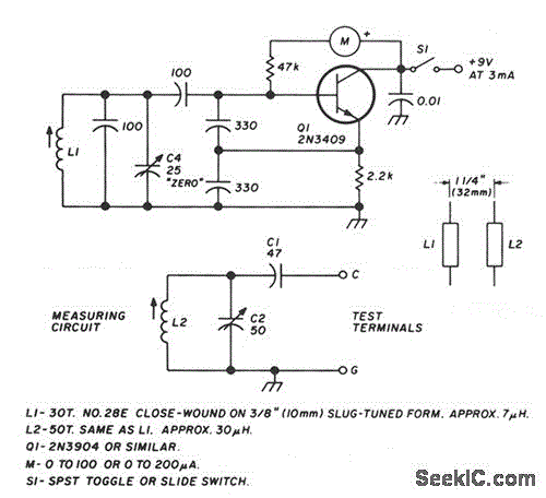
LC CHECKER
The circuit operates on the principle of the grid-dip or absorption effect, which takes place when a parallel resonant circuit is coupled to an oscillator operating at the same frequency. Transistor Q1 functions within a standard Colpitts oscillator circuit, maintaining...
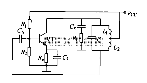
Inductance feedback oscillator circuit
A feedback oscillator circuit utilizing inductance is presented, featuring the 3DG3 transistor. The component parameters reference values include: 1) transistors 3DG6, 2) resistances R1 at 91 kΩ, R2 at 11 kΩ, and R3 unspecified, 3) capacitance values of C at...
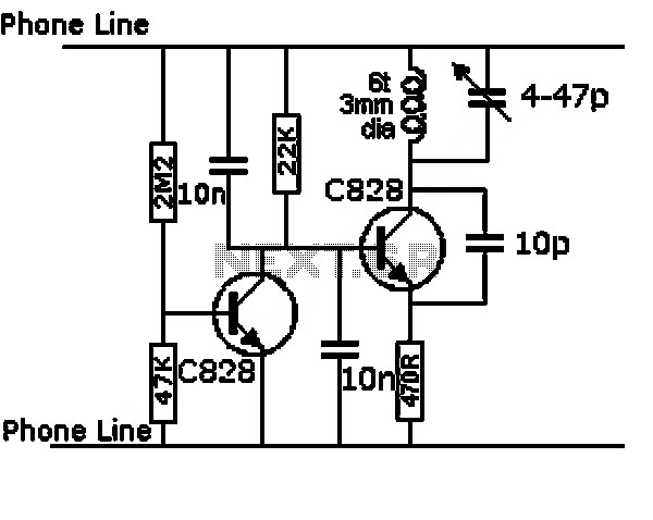
The Metal Detector Circuit
This design has not been referred to as a GOLD detector, as that term is reserved for more complex devices capable of distinguishing gold from other metals. There is a significant difference between detecting gold and ordinary metals, known as...

A practical MS Decoder Circuit
The schematic diagram of the MS Decoder may appear complex, but it is relatively straightforward. Initially, both the Mid and Side signals are buffered using unity gain inverting buffers, which are constructed around IC1b and IC2b. This buffering serves two...
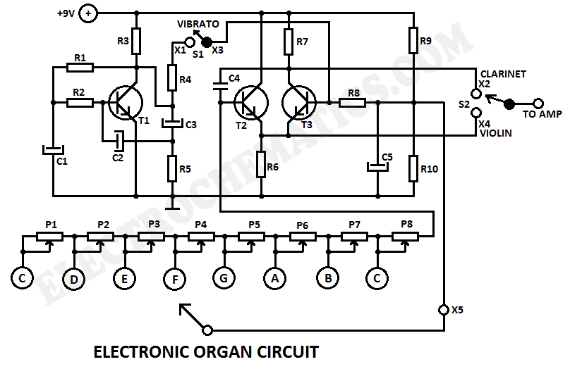
Electronic Organ Circuit
This electronic organ circuit is straightforward to construct and primarily consists of an emitter-coupled oscillator formed by transistors T2 and T3. A square wave voltage can be obtained from the collector of T3 (X2), which imparts a clarinet-like quality to...
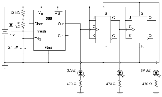
3-Bit Binary counter
This circuit utilizes two J-K flip-flops to create a three-bit binary counter, deviating from the conventional method of employing three flip-flops—one for each binary bit. In this design, the clock pulse from a 555 timer output serves as a bit...
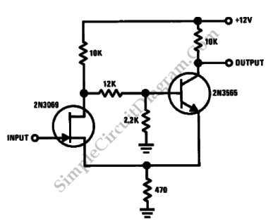
Discrete Schmitt Trigger
This is a Schmitt trigger circuit. This circuit produces a simple comparator action. It is emitter-coupled. This circuit has a distinct hysteresis loop.
The Schmitt trigger circuit is a fundamental electronic component utilized for signal conditioning, providing a means to convert...
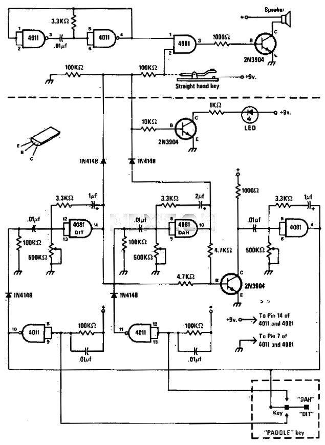
Code practice oscillator
The circuit comprises a basic oscillator (above the dashed line) and an automatic keyer (below the dashed line). The unit can be utilized with either a straight hand key or a paddle key for automatic operation.
The described circuit integrates two...
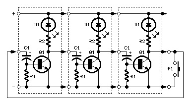
LEDs or Lamps Sequencer
Very simple, versatile modular design. The purpose of this circuit was to create a ring in which LEDs or Lamps illuminate sequentially. Its main feature is a high versatility: you can build a loop containing any number of LEDs or...