


220 Volt Disco Lamp circuit
#disco lamp
#sound activated
#220V
#lighting control
#musical trigger
#automated lighting
#high power amplifier
#lamp circuit
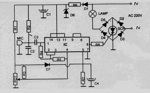
Description: This disco lamp circuit is not a voice-operated switch (VOX) because it cannot differentiate between musical sounds and human voices. Instead, it is sound-activated. An interesting application of this circuit is to control disco lighting automatically using the musical sound from a high-power amplifier when the music signal dominates the sound space. The disco lamp circuit schematic diagram is provided below. Either a moving coil microphone or a condenser microphone can be used for this circuit. It is important to ensure that the electrolytic capacitor is rated for 16 volts or more. The potentiometer depicted in the schematic diagram is utilized to adjust the gain of the pre-amplification stage. This potentiometer can be adjusted to achieve the appropriate sound level at which the relay will be activated.
The disco lamp circuit operates based on sound activation rather than voice recognition. The core of the circuit comprises a microphone that captures ambient sound, which can be either a moving coil or a condenser type. The choice between these microphones depends on the desired sensitivity and frequency response, with condenser microphones generally offering a broader range and better sensitivity to subtle sounds.
Upon capturing sound, the microphone converts acoustic energy into an electrical signal. This signal is then fed into a pre-amplification stage, which is critical for boosting the weak microphone signal to a usable level. The potentiometer in this stage allows for fine-tuning of the gain, enabling the user to adjust the sensitivity of the circuit based on the ambient noise level or the specific requirements of the application.
The amplified signal is then processed to determine if it exceeds a certain threshold, which indicates that a significant sound event, such as music, is occurring. When the signal surpasses this threshold, it triggers a relay that controls the power to the disco lights. The relay acts as a switch, turning the lights on or off in response to the detected sound level.
To ensure reliable operation, it is essential to use an electrolytic capacitor rated for at least 16 volts, which is crucial for filtering and stabilizing the power supply to the circuit components. Proper capacitor selection helps to prevent damage from voltage spikes and ensures consistent performance.
In summary, this circuit provides an effective method for synchronizing lighting effects with music, creating an engaging atmosphere in various settings such as parties or events. The design is straightforward, making it accessible for hobbyists and electronics enthusiasts who wish to enhance their audio-visual experiences.This disco lamp circuit is not a voice operated switch (VOX) because this circuit is too dumb to differentiate between musical sound or human voice. This is rather a sound activated than voice activated. One interesting application is to control your disco lighting automatically by the musical sound from high power amplifier, when the music signal
is dominating the sound space. The disco lamp circuit schematic diagram is shown below. You can use either moving coil microphone or condenser microphone for this circuit. Make sure the electrolytic capacitor is rated for 16 volt or more. The potentiometer shown in the schematic diagram is used to adjust the gain of the pre-amplification. You can adjust this potentiometer to get a proper sound level where the relay would be activated.
The disco lamp circuit operates based on sound activation rather than voice recognition. The core of the circuit comprises a microphone that captures ambient sound, which can be either a moving coil or a condenser type. The choice between these microphones depends on the desired sensitivity and frequency response, with condenser microphones generally offering a broader range and better sensitivity to subtle sounds.
Upon capturing sound, the microphone converts acoustic energy into an electrical signal. This signal is then fed into a pre-amplification stage, which is critical for boosting the weak microphone signal to a usable level. The potentiometer in this stage allows for fine-tuning of the gain, enabling the user to adjust the sensitivity of the circuit based on the ambient noise level or the specific requirements of the application.
The amplified signal is then processed to determine if it exceeds a certain threshold, which indicates that a significant sound event, such as music, is occurring. When the signal surpasses this threshold, it triggers a relay that controls the power to the disco lights. The relay acts as a switch, turning the lights on or off in response to the detected sound level.
To ensure reliable operation, it is essential to use an electrolytic capacitor rated for at least 16 volts, which is crucial for filtering and stabilizing the power supply to the circuit components. Proper capacitor selection helps to prevent damage from voltage spikes and ensures consistent performance.
In summary, this circuit provides an effective method for synchronizing lighting effects with music, creating an engaging atmosphere in various settings such as parties or events. The design is straightforward, making it accessible for hobbyists and electronics enthusiasts who wish to enhance their audio-visual experiences.This disco lamp circuit is not a voice operated switch (VOX) because this circuit is too dumb to differentiate between musical sound or human voice. This is rather a sound activated than voice activated. One interesting application is to control your disco lighting automatically by the musical sound from high power amplifier, when the music signal
is dominating the sound space. The disco lamp circuit schematic diagram is shown below. You can use either moving coil microphone or condenser microphone for this circuit. Make sure the electrolytic capacitor is rated for 16 volt or more. The potentiometer shown in the schematic diagram is used to adjust the gain of the pre-amplification. You can adjust this potentiometer to get a proper sound level where the relay would be activated.
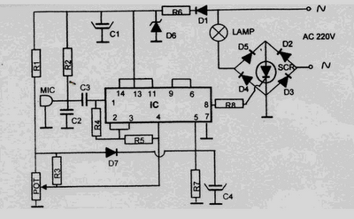
220 volt disco lamp circuit
This 220 Volt disco lamp circuit is not a voice switch (VOX), as it cannot differentiate between musical sounds and human voices. Instead, it functions as a sound-activated device. An interesting application of this circuit is to control the lighting...
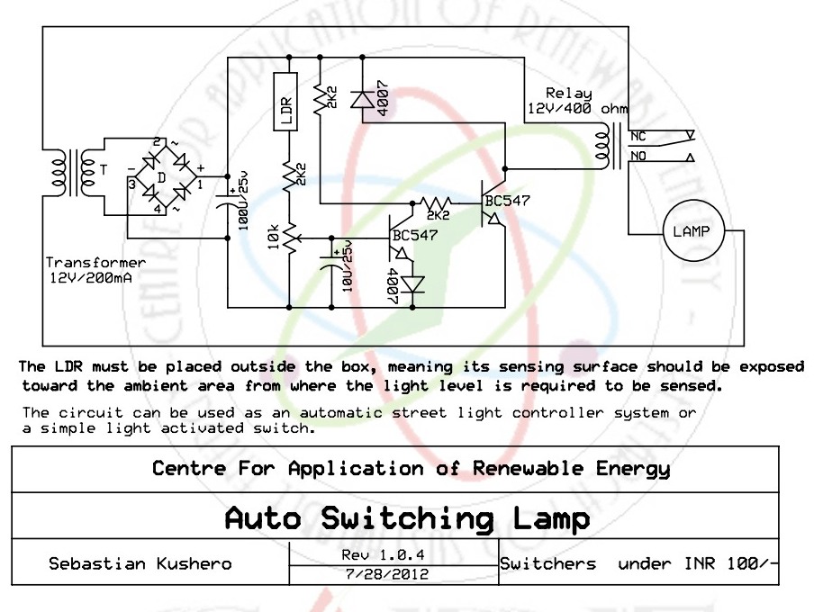
Sound Activated Switch Circuit
This sound-activated switch allows for sound control, which can be beneficial not only for robotic applications but also for home automation.
The sound-activated switch operates by detecting specific sound frequencies or patterns, enabling the user to control various devices or systems...
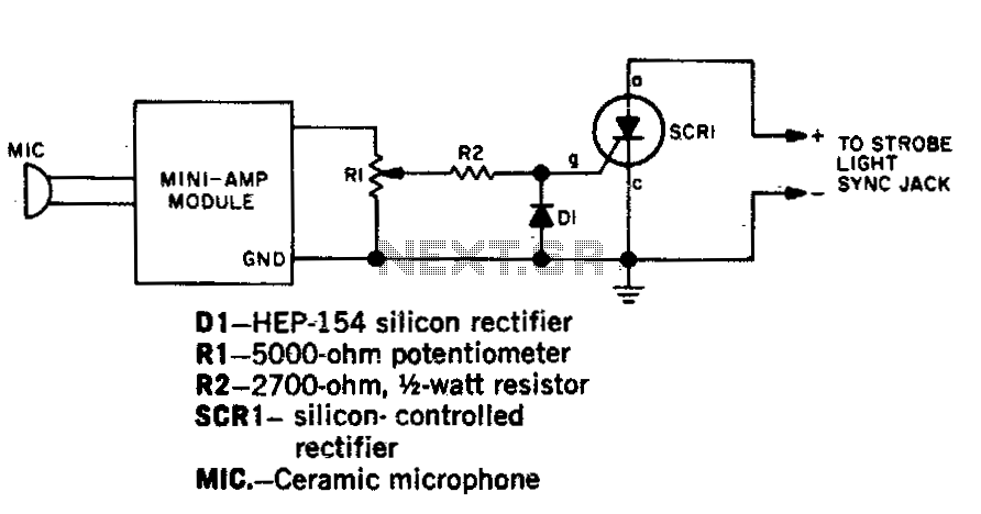
Sound activated strobe trip
Capture strobe-flash images at the precise moment a pin punctures a balloon, a hammer shatters a lamp bulb, or a bullet exits a firearm. Utilize a transistor amplifier rated at 1 watt or less, which must include an output transformer....
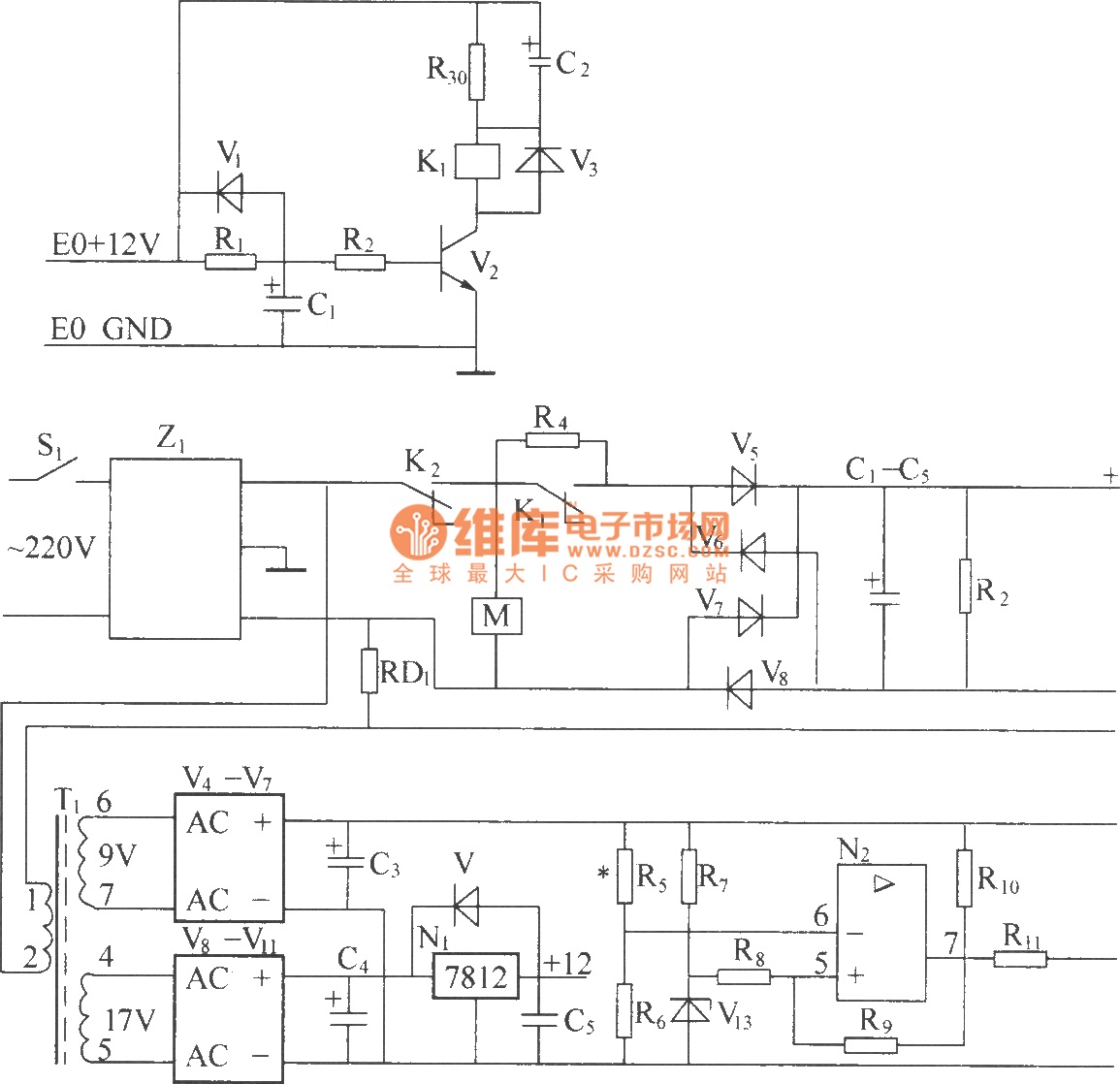
DZW75-48/5050II input circuit
220V (5Hz) alternating voltage passes through the Z1 circuit filter, which filters the signal before sending it to the connection point of the AC over-voltage and under-voltage protection relay K2. During normal operation, the K2 connection point should be closed,...
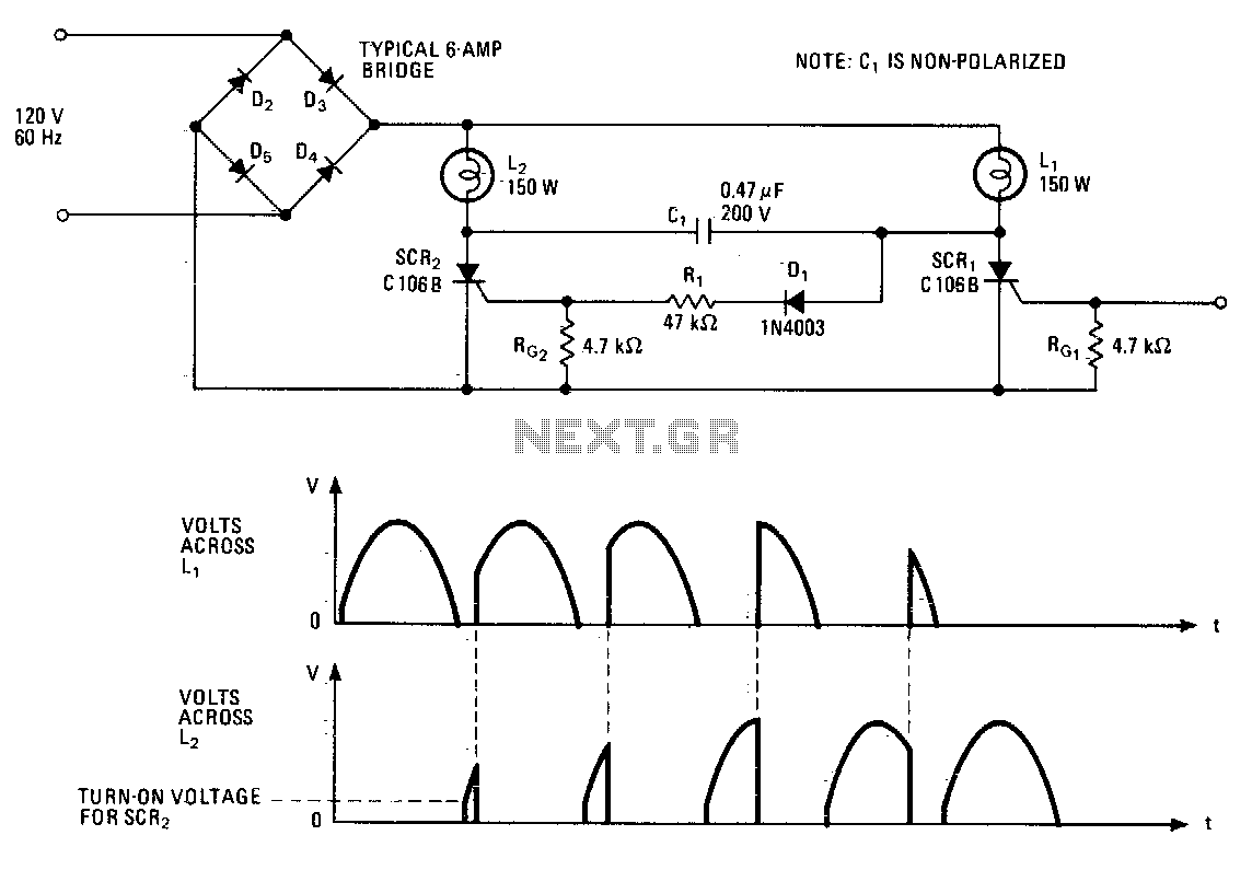
Complementary lighting control
This lighting control unit will gradually decrease the brightness of one lamp while simultaneously increasing the brightness of another. The two loads maintain precise tracking without the need for manual adjustments. The gate of SCR1, a silicon-controlled rectifier, is activated...
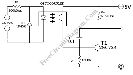
220V Power Line Interface
This is a simple 220V power interface circuit. This circuit is used as an interface for monitoring electrical devices and equipment using a computer.
The 220V power interface circuit serves as a critical connection point between high-voltage electrical systems and low-voltage...
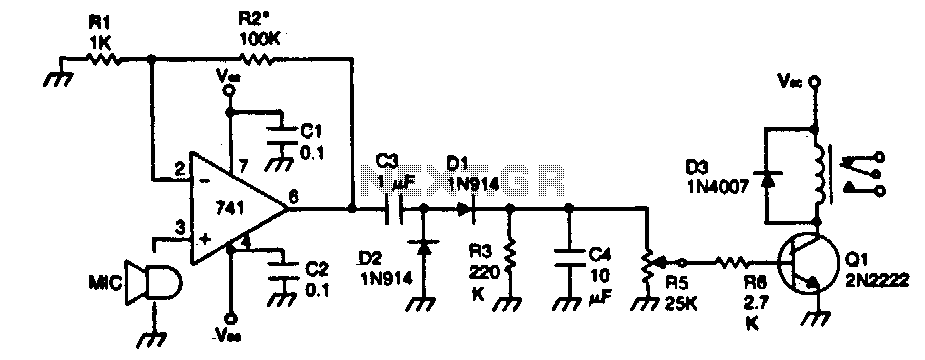
Sound activated relay
The device remains dormant (in an off condition) until a sound activates it. The input stage consists of a 741 operational amplifier configured as a non-inverting audio amplifier with a gain of approximately 100. To increase the gain, the value...
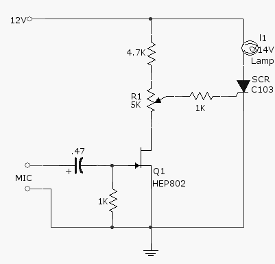
sound activated lamp relay switch
This simple circuit, as shown in the schematic diagram, activates a switch using sound. It can be utilized for various applications, such as an automatic sound-controlled disco light or a car's LED light show. The transistor Q1 amplifies the audio...
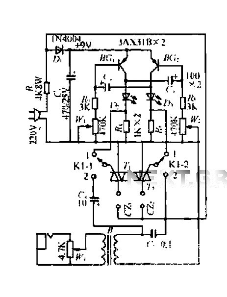
A simple control circuit Lantern
A 220V mains power supply is reduced using a control circuit designed by N. Guanidine D. Yi. The circuit features a spike Bode and provides a +9V voltage supply. It includes components such as a control port (G), a transistor...