


220 Volts Flashing Lamps
#flashing lamps
#SCR
#timing circuit
#Christmas tree lights
#220V
#trigger circuit
#capacitor
#resistors
#flashing frequency
#thermally-activated switches
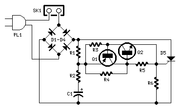
Description: This circuit is designed to serve as a reliable substitute for thermally-activated switches used in Christmas tree lamp-flashing applications. The configuration comprising Q1, Q2, and associated resistors activates the SCR. Timing is managed by R1, R2, and C1. To adjust the flashing frequency, it is advised not to alter the values of R1 and R2; instead, modify the capacitance of C1, ranging from 100 to 2200 µF. Optimal performance is achieved with C1 values of 470 or 1000 µF and R4 values of 12K or 10K. Given the low current consumption typical of 10 or 20 lamp series loops for Christmas trees (approximately 60mA at 220V for a 20 lamp series loop), small and cost-effective SCR devices can be utilized, such as the C106D1 (400V, 3.2A) or TICP106D (400V, 2A), both of which come in a TO92 package. If these devices are unavailable, Triacs can also be employed, allowing the circuit to function with relatively higher-power components. The TIC206M (600V, 4A) is a recommended Triac type, although many others may also be suitable. It is important to note that regardless of the use of a Triac, the diode bridge D1-D4 is always necessary.
This circuit functions as a flashing controller for Christmas tree lights, effectively replacing traditional thermal switches with a solid-state solution. The primary components include two transistors (Q1 and Q2) that act as a trigger mechanism for the Silicon Controlled Rectifier (SCR). The resistors R1 and R2, along with the capacitor C1, create a timing circuit that dictates the flash rate of the lights.
To fine-tune the flashing frequency, the capacitance of C1 should be adjusted rather than the resistors R1 and R2. This design choice allows for a wider range of flashing frequencies by simply changing the capacitor's value within the specified limits. The recommended values of C1 (470 or 1000 µF) and R4 (12K or 10K) have been determined through testing to provide the best performance in this application.
The circuit is designed to operate with minimal power, making it suitable for the low current requirements of typical Christmas tree light setups, which draw about 60mA at 220V. This low power consumption enables the use of compact and economical SCRs, such as the C106D1 or TICP106D, both of which are capable of handling the circuit's demands without overheating or failing.
In instances where these SCRs are not available, the circuit can be adapted to utilize Triacs, which are also effective for this application. The TIC206M Triac is a commonly used component that can replace the SCR while maintaining the circuit's functionality. The inclusion of the diode bridge (D1-D4) is critical to the circuit's operation, ensuring that the current is appropriately managed regardless of whether an SCR or Triac is used. This diode bridge allows for the necessary rectification and protection of the circuit components, contributing to the overall reliability and performance of the flashing controller.This circuit is intended as a reliable replacement to thermally-activated switches used for Christmas tree lamp-flashing. The device formed by Q1, Q2 and related resistors triggers the SCR. Timing is provided by R1, R2 & C1. To change flashing frequency don`t modify R1 and R2 values: set C1 value from 100 to 2200 µF instead.
Best performances are o btained with C1=470 or 1000 µF and R4=12K or 10K. Due to low consumption of normal 10 or 20 lamp series-loops intended for Christmas trees (60mA @ 220V typical for a 20 lamp series-loop), very small and cheap SCR devices can be used, e. g. C106D1 (400V 3. 2A) or TICP106D (400V 2A), this last and the suggested P0102D devices having TO92 case. If you are unable to find these devices you can use Triacs instead. In this case the circuit operates also with relatively powerful devices. A recommended Triac type is the ubiquitous TIC206M (600V 4A) but many others can work. Note that in spite of the Triac, diode bridge D1-D4 is in any case necessary.
This circuit functions as a flashing controller for Christmas tree lights, effectively replacing traditional thermal switches with a solid-state solution. The primary components include two transistors (Q1 and Q2) that act as a trigger mechanism for the Silicon Controlled Rectifier (SCR). The resistors R1 and R2, along with the capacitor C1, create a timing circuit that dictates the flash rate of the lights.
To fine-tune the flashing frequency, the capacitance of C1 should be adjusted rather than the resistors R1 and R2. This design choice allows for a wider range of flashing frequencies by simply changing the capacitor's value within the specified limits. The recommended values of C1 (470 or 1000 µF) and R4 (12K or 10K) have been determined through testing to provide the best performance in this application.
The circuit is designed to operate with minimal power, making it suitable for the low current requirements of typical Christmas tree light setups, which draw about 60mA at 220V. This low power consumption enables the use of compact and economical SCRs, such as the C106D1 or TICP106D, both of which are capable of handling the circuit's demands without overheating or failing.
In instances where these SCRs are not available, the circuit can be adapted to utilize Triacs, which are also effective for this application. The TIC206M Triac is a commonly used component that can replace the SCR while maintaining the circuit's functionality. The inclusion of the diode bridge (D1-D4) is critical to the circuit's operation, ensuring that the current is appropriately managed regardless of whether an SCR or Triac is used. This diode bridge allows for the necessary rectification and protection of the circuit components, contributing to the overall reliability and performance of the flashing controller.This circuit is intended as a reliable replacement to thermally-activated switches used for Christmas tree lamp-flashing. The device formed by Q1, Q2 and related resistors triggers the SCR. Timing is provided by R1, R2 & C1. To change flashing frequency don`t modify R1 and R2 values: set C1 value from 100 to 2200 µF instead.
Best performances are o btained with C1=470 or 1000 µF and R4=12K or 10K. Due to low consumption of normal 10 or 20 lamp series-loops intended for Christmas trees (60mA @ 220V typical for a 20 lamp series-loop), very small and cheap SCR devices can be used, e. g. C106D1 (400V 3. 2A) or TICP106D (400V 2A), this last and the suggested P0102D devices having TO92 case. If you are unable to find these devices you can use Triacs instead. In this case the circuit operates also with relatively powerful devices. A recommended Triac type is the ubiquitous TIC206M (600V 4A) but many others can work. Note that in spite of the Triac, diode bridge D1-D4 is in any case necessary.
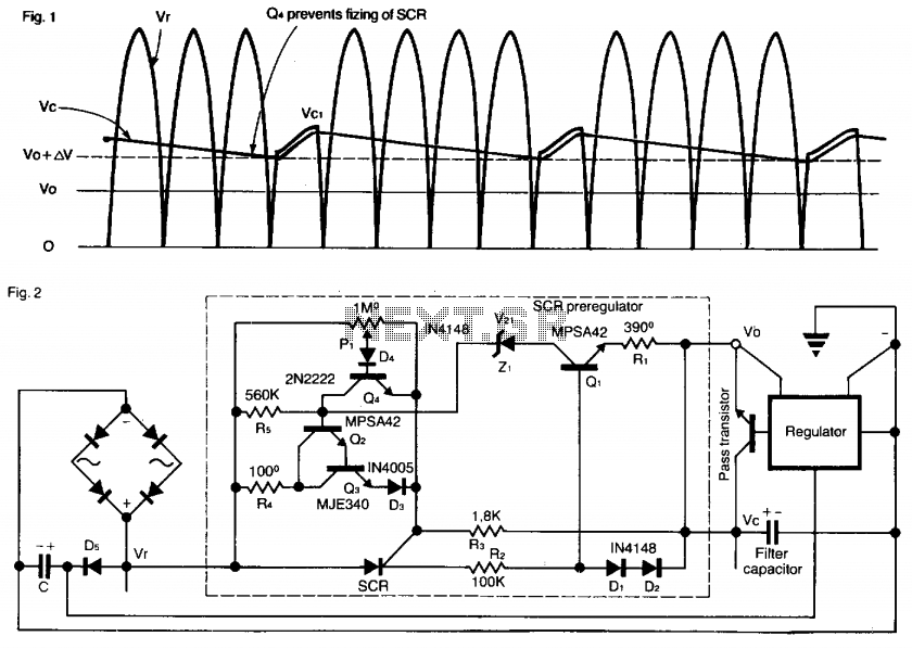
Preregulator for power supply
This SCR pre-regulator maintains the filter capacitor voltage (Vc) in a variable output power supply at a few volts above the output voltage (V0). The advantages include reduced heat dissipation by the pass transistor, resulting in a smaller heatsink, cooler...
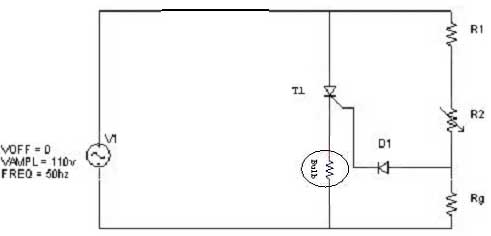
triggering circuit
Simple resistor and diode combinations are used to trigger and control silicon-controlled rectifiers (SCRs) across the full 180-degree electrical range, exhibiting reliable performance at commercial temperatures. These circuits function optimally when SCRs possess relatively high gate sensitivities. In this configuration,...
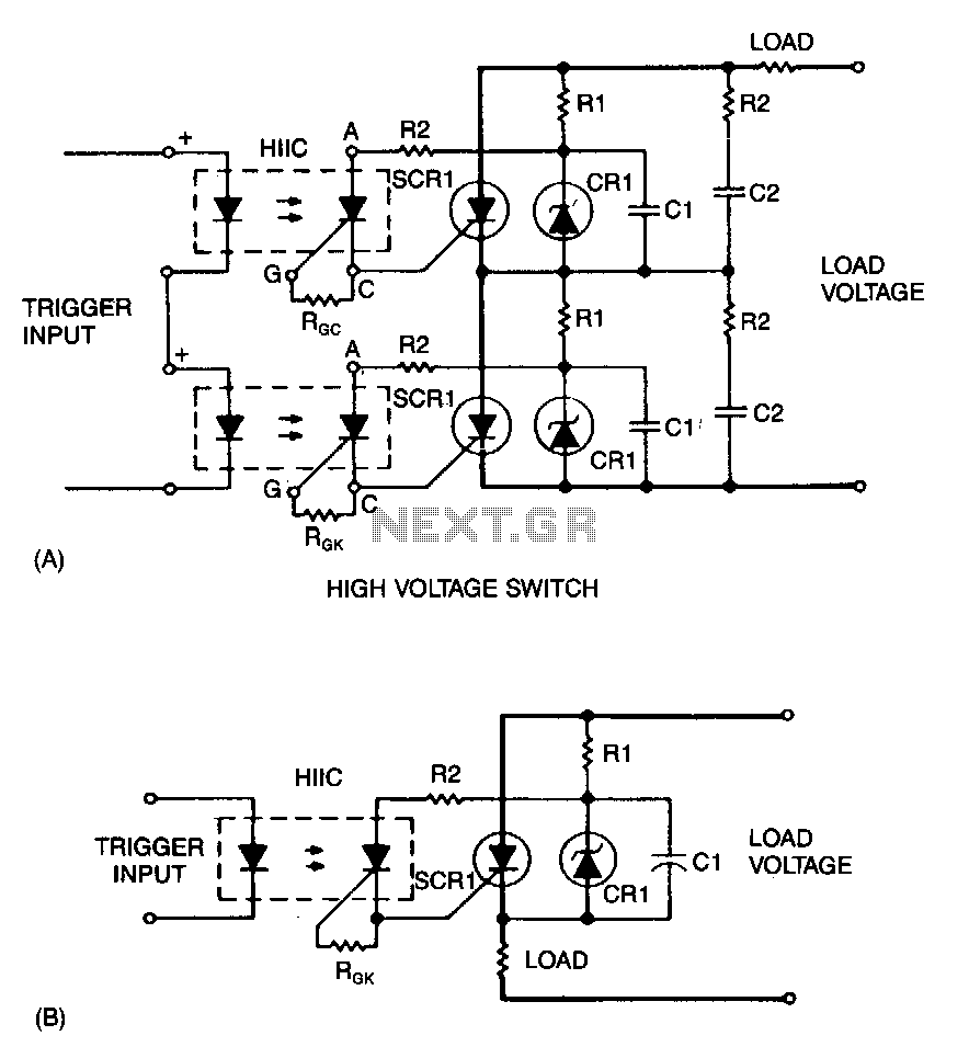
Triggering-scr-series
A snubber circuit consisting of R2 and C2 may be necessary, as R1 and C1 are designed for optimized triggering rather than for dV/dt protection. Fiber-optic pairs can be utilized with discrete SCRs to switch high voltages. A photonic coupler...
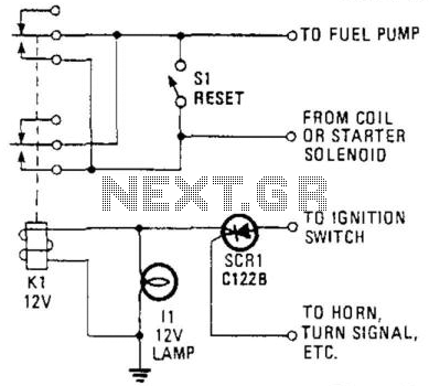
Auto Ignition Cut-Off
This circuit utilizes a combination of a silicon-controlled rectifier (SCR) and a relay to interrupt the ignition system unless a positive voltage is applied to the gate of the SCR. This configuration serves as an anti-theft device, as the vehicle...
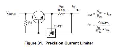
Capacitor Charging Circuit
This Korean SuperCap OEM supports usage in series configurations. Consider whether the implementation will be manual or automatic, such as with a smart battery charger or a power fail backup circuit. It is essential to balance the voltage and provide...

Modified 220V Dimmer Circuit
Note: Do not build or use this if you do not have any knowledge in electrical or electronics. This project is not safe for beginners, and the voltage involved is dangerous and can cause electrocution. Do not exceed the load...
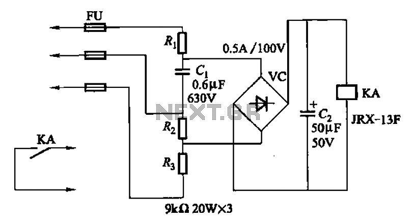
The second phase alarm circuit
A capacitor C1 and resistors R1-R3 form a negative sequence voltage filtration device. The resistors and capacitors must meet the following requirements: R1, R2, R3 = 5.5/C1 (KN). The relationship between the resistance and capacitance values is arbitrary. Capacitor selection...
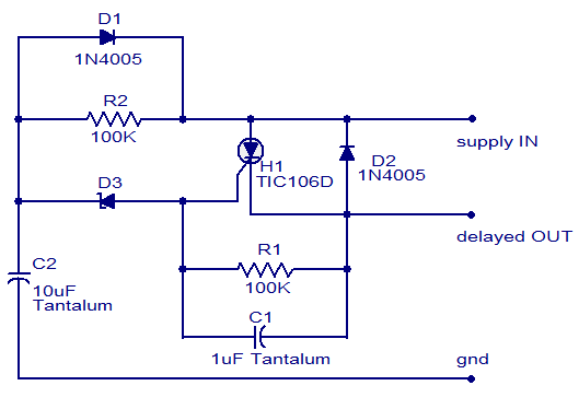
Simple DC power delay circuit
The circuit diagram presented is of a straightforward DC power delay circuit utilizing a silicon-controlled rectifier (SCR). This circuit is quite useful and can be applied in various scenarios. The operation of this circuit is uncomplicated. Upon the application of...
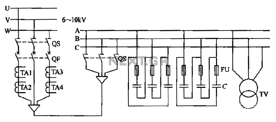
High-pressure centralized compensation capacitor circuit
The compensation system is designed to focus on a high-pressure, high-voltage capacitor bank installed in the substation 6-10 kV bus. Compensation can only be implemented in this manner for the 6-10 kV bus before the reactive power on the line,...