


220v ac operated christmas light star
#220V AC
#Christmas light
#LED
#triac
#multivibrator
#transistors
#zener diode
#resistors
#capacitors
#diodes
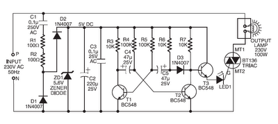
Description: Components such as resistors R1 and R2, capacitors C1, C2, and C3, diodes D1 and D2, and a zener diode ZD1 are utilized to create a stable 5V DC supply voltage that delivers the necessary current to operate the multivibrator circuit and trigger triac BT136 through LED1. The multivibrator circuit is built using two BC548 transistors (T1 and T2) along with additional passive components. The frequency of the multivibrator circuit is regulated by capacitors C4 and C5 and resistors R3 to R7. The output of the multivibrator circuit connects to transistor T3, which subsequently drives the triac via LED1. During the positive half cycles of the multivibrator's output, transistor T3 activates triac BT136, causing the lamp to illuminate. The estimated cost of this circuit is Rs 75.
The circuit design employs a combination of discrete components to achieve a reliable 5V DC supply, which is crucial for the operation of the multivibrator and the triggering of the triac. The inclusion of diodes D1 and D2 ensures proper rectification and protection against reverse polarity, while the zener diode ZD1 stabilizes the voltage to maintain a consistent output under varying load conditions.
The multivibrator configuration, consisting of two BC548 transistors, operates in an astable mode. The resistors R3 through R7 and capacitors C4 and C5 dictate the timing characteristics, allowing for precise control over the output frequency. This frequency modulation is essential for the desired operation of the connected load, in this case, a lamp.
Transistor T3 serves as a switch that amplifies the output signal from the multivibrator to drive the triac BT136. The LED1 acts as an indicator, providing visual feedback when the triac is activated. The triac, once triggered, allows current to flow through the connected lamp, thus illuminating it during the positive half cycles of the output signal.
The overall design is cost-effective, with an estimated total expense of Rs 75, making it an economical solution for applications requiring a controlled lighting mechanism. The schematic effectively integrates the components to ensure reliable performance and operational efficiency.Components like resistors R1 and R2, capacitors C1, C2, and C3, diodes D1 and D2, and zener ZD1 are used to develop a fairly steady 5V DC supply voltage that provides the required current to operate the multivibrator circuit and trigger triac BT136 via LED1. The multivibrator circuit is constructed using two BC548 transistors (T1 and T2) and some passive components. The frequency of the multivibrator circuit is controlled by capacitors C4 and C5 and resistors R3 through R7. The output of the multivibrator circuit is connected to transistor T3, which, in turn, drives the triac via LED1.
During positive half cycles of the multivibrator`s output, transistor T3 energises triac BT136 and the lamp glows. This circuit is estimated to cost Rs 75.
The circuit design employs a combination of discrete components to achieve a reliable 5V DC supply, which is crucial for the operation of the multivibrator and the triggering of the triac. The inclusion of diodes D1 and D2 ensures proper rectification and protection against reverse polarity, while the zener diode ZD1 stabilizes the voltage to maintain a consistent output under varying load conditions.
The multivibrator configuration, consisting of two BC548 transistors, operates in an astable mode. The resistors R3 through R7 and capacitors C4 and C5 dictate the timing characteristics, allowing for precise control over the output frequency. This frequency modulation is essential for the desired operation of the connected load, in this case, a lamp.
Transistor T3 serves as a switch that amplifies the output signal from the multivibrator to drive the triac BT136. The LED1 acts as an indicator, providing visual feedback when the triac is activated. The triac, once triggered, allows current to flow through the connected lamp, thus illuminating it during the positive half cycles of the output signal.
The overall design is cost-effective, with an estimated total expense of Rs 75, making it an economical solution for applications requiring a controlled lighting mechanism. The schematic effectively integrates the components to ensure reliable performance and operational efficiency.Components like resistors R1 and R2, capacitors C1, C2, and C3, diodes D1 and D2, and zener ZD1 are used to develop a fairly steady 5V DC supply voltage that provides the required current to operate the multivibrator circuit and trigger triac BT136 via LED1. The multivibrator circuit is constructed using two BC548 transistors (T1 and T2) and some passive components. The frequency of the multivibrator circuit is controlled by capacitors C4 and C5 and resistors R3 through R7. The output of the multivibrator circuit is connected to transistor T3, which, in turn, drives the triac via LED1.
During positive half cycles of the multivibrator`s output, transistor T3 energises triac BT136 and the lamp glows. This circuit is estimated to cost Rs 75.
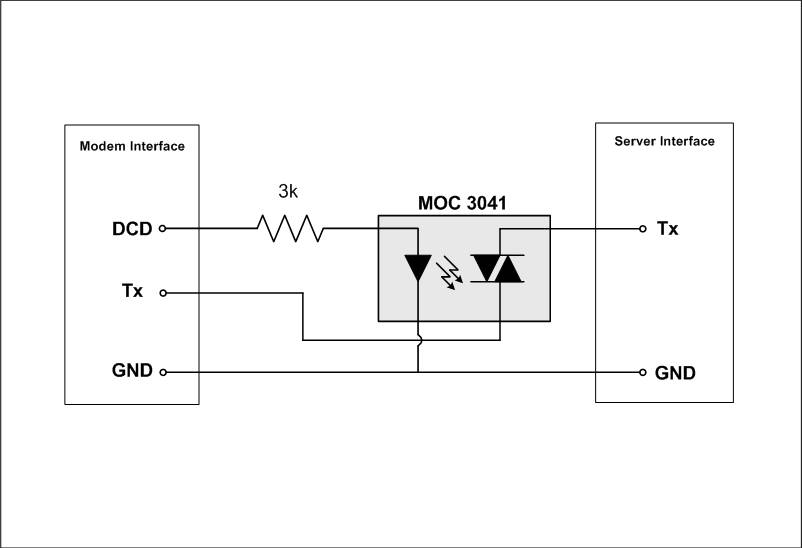
triac Optotriac doesnt turn off
There are no issues with powering it on, but after disconnecting the input (with no input current), the triac remains on. The load operates at standard RS-232 voltages (+/- 12V) with a speed of 56k. It was mentioned that an...
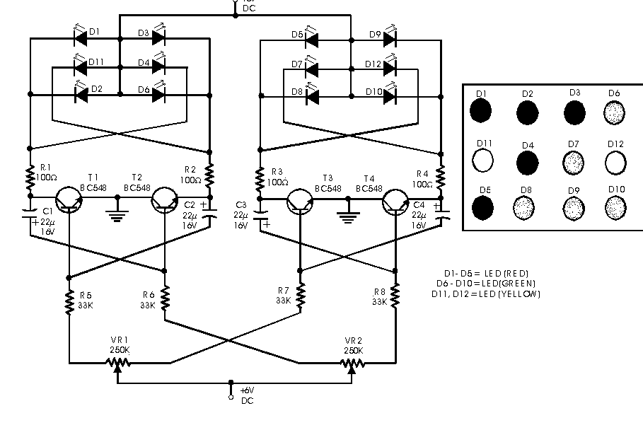
Dancing LED's circuit
Here is a simple circuit which can be used for decoration purposes or as an indicator. Flashing or dancing speed of LEDs can be adjusted and various dancing patterns of lights can be formed. The circuit consists of two astable...
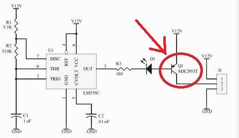
LED Flasher Schematic
Here is the new flasher circuit schematic. It consists of a 555 timer circuit and a power transistor. The power transistor is likely over-specified, as it is rated at 10A, but it is the component that was available. The values...
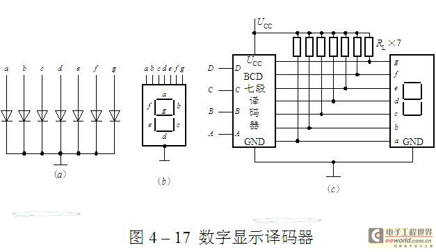
BCD seven sections of nixie tubes reveal the decoder circuit
The luminescent diode (LED) is constructed from gallium arsenide (GaAs), a specialized semiconductor material, and gallium arsenide phosphide. It can be used individually or assembled into segment-type or lattice LED display devices. The display unit consists of a sectional type...
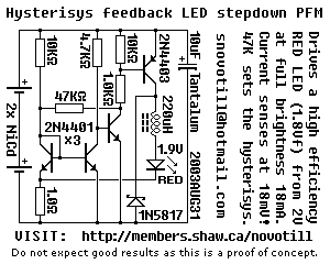
LED stepdown power supply
Below is a proof of concept circuit which needs improvement. The part values shown will run a high efficiency red LED with a Vf of 1.9V from only 2 nicads, right down to 2 volts. For a white LED you...
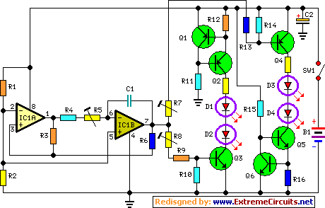
Fading Leds Circuit
This circuit operates two LED strips in pulsing mode, where one LED strip transitions from an off state to gradually lighting up, then dimming, while the other LED strip performs the opposite action. Each strip can consist of 2 to...
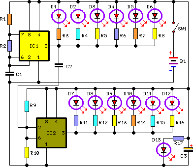
Bicycle Back Safety Light Circuit Schematic Circuit
This circuit is designed to provide a clearly visible light using 13 high-efficiency flashing LEDs arranged in a pseudo-rotating manner. Its low voltage, low battery drain operation, and compact size make it suitable for mounting on bicycles as a backlight...
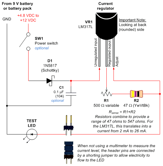
Constant Current LED Tester
Most circuits utilize a 5 V regulated power supply for microcontrollers and sensors, as 8-bit microcontrollers operate efficiently at this voltage. The 5 V supply is adequate for powering white LEDs, thus the specific voltage requirements of individual LEDs are...

Multi-color LED driver
Have you ever wondered how many different colors can illuminate an LED? One, two, or maybe three? By constructing this simple circuit, you will discover much more. The key component in this design is a dual LED. This component consists...