


5G169 holiday lights integrated circuit
#holiday lights
#integrated circuit
#bridge rectifier
#voltage regulator
#AC to DC
#LED
#filter circuit
#6V power
#decorative lighting
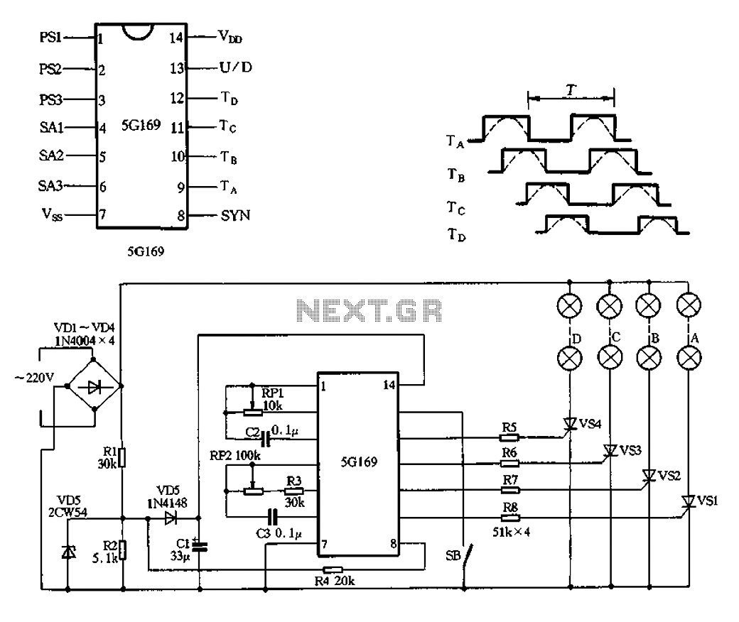
Description: The circuit features an AC input from VDI, which is converted to pulsating DC power using a VD4 full-wave bridge rectifier to power four lights. Resistors R1 and R2, along with diode VD5, form a simple circuit, while VD6 serves as a voltage regulator. Capacitor C1 filters the output to approximately 6V DC. The power supply is designed to manage voltage ripple, which operates at a frequency of 100Hz, twice that of the alternating current input. The signal is synchronized through R4, which injects a synchronization signal into the manifold. Switch SB controls the forward and reverse operation; when open, the circuit operates in positive mode, and when closed, it reverses the circulation. The configuration in Figure 2-102 illustrates the forward loop, with pin outputs 9 to 12. The dashed line denotes the changing arc light levels, which can be adjusted within a range of 100ms to 5s.
The circuit operates by first converting the alternating current (AC) from the VDI source into direct current (DC) using a full-wave bridge rectifier comprised of four diodes, designated as VD4. This rectification process results in a pulsating DC output that is suitable for powering multiple lighting elements. The output voltage is smoothed and regulated by the combination of components R1, R2, VD5, and VD6. Resistors R1 and R2 help in current limiting and voltage division, while VD5 acts as a simple diode to ensure current flows in the correct direction. VD6 is specifically utilized as a voltage regulator, maintaining the output voltage at a stable 6V DC despite variations in the load or input voltage.
Capacitor C1 plays a crucial role in filtering the pulsating DC output, effectively reducing ripple voltage and providing a more stable DC supply. The ripple frequency, which is double the input AC frequency, is noted to be 100Hz. The circuit includes a mechanism for synchronization, achieved through resistor R4, which injects a signal into the power supply manifold to ensure consistent operation across the circuit.
The operation of the circuit can be controlled using switch SB, which toggles between forward and reverse modes. In the forward mode, the switch is open, allowing current to flow in a designated direction. Conversely, closing the switch reverses the current flow, altering the operation of the connected lights. The configuration detailed in Figure 2-102 outlines the forward loop, indicating the pin outputs from 9 to 12, which are integral to the circuit's functionality. The dashed lines in the figure represent the varying arc light levels, which can be adjusted over a period ranging from 100 milliseconds to 5 seconds, providing flexibility in light intensity and timing for the application.AC by VDI ~ VD4 full-wave bridge rectifier output pulsating DC power for four lights. Rl, R2, VD5 simple composition and VD6 regulator circuit, Cl filtered output by about 6V D C power supply manifold. VD6 here isolators, so to get across R2 6V full-wave pulsating direct current voltage ripple frequency of the alternating current to twice that of 100Hz, 100Hz for this signal by R4 injection manifold 8 feet as a synchronization signal. FIG. SB is forward and reverse control switch, SB open cycle is positive; SB closed reverse circulation. Figure 2-102 is the forward loop convolutions 9 to 12-pin output, the dashed line indicates the arc light levels change, period r adjustable range lOOms ~ 5s.
The circuit operates by first converting the alternating current (AC) from the VDI source into direct current (DC) using a full-wave bridge rectifier comprised of four diodes, designated as VD4. This rectification process results in a pulsating DC output that is suitable for powering multiple lighting elements. The output voltage is smoothed and regulated by the combination of components R1, R2, VD5, and VD6. Resistors R1 and R2 help in current limiting and voltage division, while VD5 acts as a simple diode to ensure current flows in the correct direction. VD6 is specifically utilized as a voltage regulator, maintaining the output voltage at a stable 6V DC despite variations in the load or input voltage.
Capacitor C1 plays a crucial role in filtering the pulsating DC output, effectively reducing ripple voltage and providing a more stable DC supply. The ripple frequency, which is double the input AC frequency, is noted to be 100Hz. The circuit includes a mechanism for synchronization, achieved through resistor R4, which injects a signal into the power supply manifold to ensure consistent operation across the circuit.
The operation of the circuit can be controlled using switch SB, which toggles between forward and reverse modes. In the forward mode, the switch is open, allowing current to flow in a designated direction. Conversely, closing the switch reverses the current flow, altering the operation of the connected lights. The configuration detailed in Figure 2-102 outlines the forward loop, indicating the pin outputs from 9 to 12, which are integral to the circuit's functionality. The dashed lines in the figure represent the varying arc light levels, which can be adjusted over a period ranging from 100 milliseconds to 5 seconds, providing flexibility in light intensity and timing for the application.AC by VDI ~ VD4 full-wave bridge rectifier output pulsating DC power for four lights. Rl, R2, VD5 simple composition and VD6 regulator circuit, Cl filtered output by about 6V D C power supply manifold. VD6 here isolators, so to get across R2 6V full-wave pulsating direct current voltage ripple frequency of the alternating current to twice that of 100Hz, 100Hz for this signal by R4 injection manifold 8 feet as a synchronization signal. FIG. SB is forward and reverse control switch, SB open cycle is positive; SB closed reverse circulation. Figure 2-102 is the forward loop convolutions 9 to 12-pin output, the dashed line indicates the arc light levels change, period r adjustable range lOOms ~ 5s.
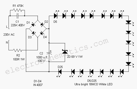
White LED Flood Lamp circuit
This white LED light illuminates the porch with cool white light. The circuit features a simple and energy-saving design. Its current consumption is practical.
The white LED light circuit is designed to provide efficient illumination while minimizing energy usage. The primary...
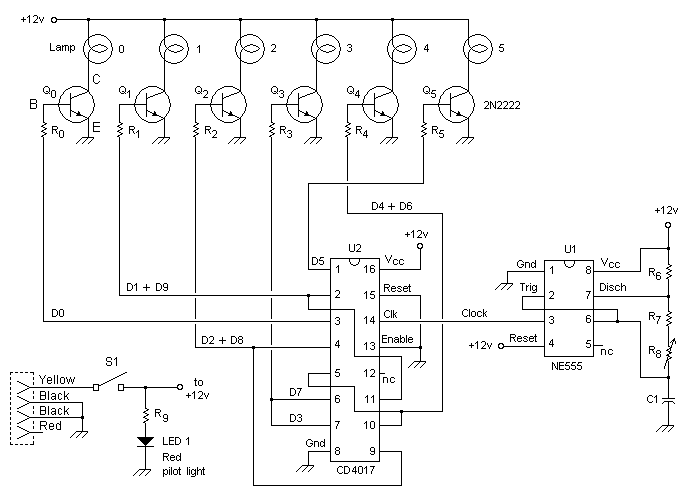
KIT CAR Lights circuit
This custom mod gives your computer the personality of KITT, the computerized car from Knight Rider TV fame. The project is a light display which imitates the dot in KITT's hood. It looks like the scanning eye of the car's...
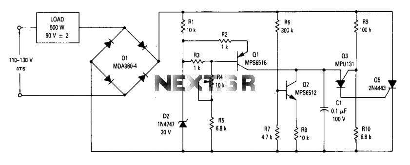
90Vrms voltage regulator
The circuit is an open-loop RMS voltage regulator designed to deliver 500 watts of power at 90 V RMS, maintaining good regulation within an input voltage range of 110-130 V RMS. When the input voltage is applied, capacitor C1 charges...
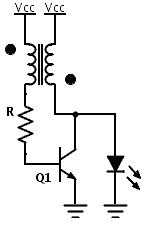
LED Boost converter Joule Thief circuit
Previously, a boost circuit was tested that enables the powering of a 3 V LED using a discharged battery (approximately 1 V or lower). This circuit consists of a single transistor, one resistor, and a small transformer with a 1:1...
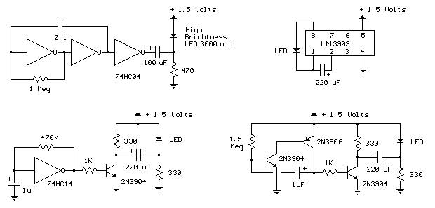
1 5 volt led flashers
The LED flasher circuits operate on a single 1.5-volt battery. The circuit on the upper right utilizes the widely used LM3909 LED flasher integrated circuit (IC) and requires only a timing capacitor and an LED.
The LM3909 is a specialized integrated...
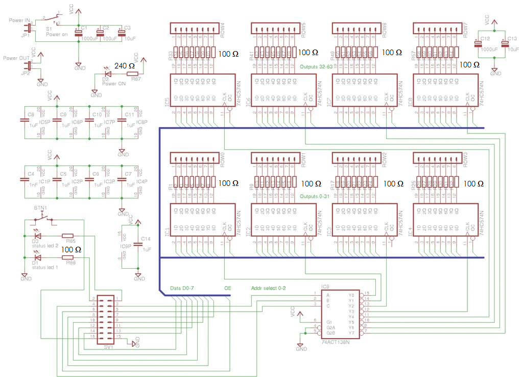
8x8x8 LED Cube
A total of 512 functional LEDs is required for the lattice assembly. These LEDs must be stable and bright. This section outlines the process for identifying faulty LEDs among the usable ones. Often, there are defective LEDs, particularly when purchased...
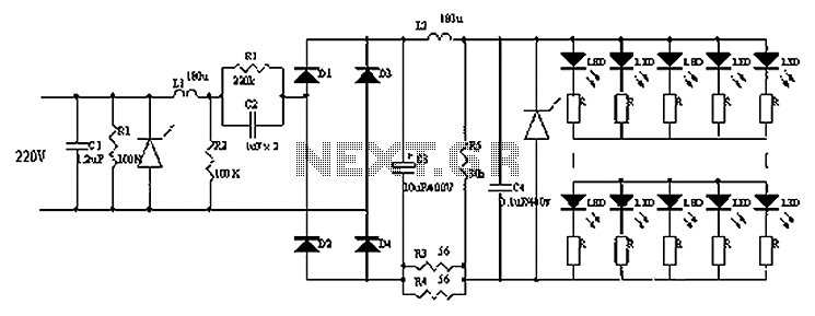
220V AC powered LED lamp drive circuit diagram
Circuits C1, R1, varistors, L1, and R2 form a filter circuit that includes a primary power supply capable of filtering out transient overvoltage inputs. The circuit also consists of C2 and R2, with additional components C3, C4, and L2. This...
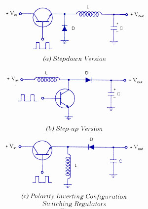
Switching Voltage Regulators-Step up Step down and polarity invert
Switching voltage regulators include step-up, step-down, and polarity-inverting configurations, along with their working principles and circuit diagrams.
Switching voltage regulators are essential components in modern electronic circuits, providing efficient voltage conversion. These regulators can be categorized into three main types: step-up...
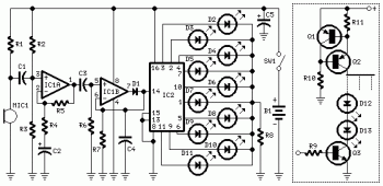
10 Dancing LEDs ElectronicCircuit Based On The LM358 IC
The following circuit illustrates a Dancing LEDs electronic circuit diagram. This circuit is based on the LM358 integrated circuit. Features: IC1A amplifies the signal.
The Dancing LEDs circuit utilizes the LM358 operational amplifier to create a visually appealing light display. The...