


6 Channel Auto Reverse Sequential Disco Running Lightss
#disco lights
#sequential lights
#auto reverse
#triac
#230V AC
#decorative bulbs
#pulse generator
#counter
#transistor
#power supply
Description: A DC supply of +5 V is obtained from a 230 V AC source. This power supply is utilized by other circuit blocks. A pulse generator operating at a specific frequency generates clock pulses. These clock pulses are counted by a counter that provides output after every 10 pulses. The counter controls transistors that are part of a triac firing circuit. The transistors trigger the triacs, which supply adequate current to the load. Decorative bulbs are used as the load for each triac. The bulbs are turned ON and OFF sequentially in both forward and reverse directions. An IC 555 functions as the pulse generator, supplying clock pulses to an IC 4017. The IC 4017 serves as the main component of the circuit, acting as a counter that outputs after every 10 pulses and drives the transistors, which subsequently activate the triacs. The triacs then deliver sufficient current to the load.
The circuit begins with a power supply that converts 230 V AC to a stable +5 V DC output, ensuring that the subsequent components operate within their required voltage specifications. This DC supply is essential for powering the pulse generator and the integrated circuits involved in the operation.
The pulse generator, implemented using an IC 555, operates in astable mode to produce a continuous stream of clock pulses. The frequency of these pulses can be adjusted by selecting appropriate resistor and capacitor values in the circuit, allowing for flexibility in the operation of the entire system. The generated clock pulses are fed into an IC 4017, which functions as a decade counter. The IC 4017 counts the incoming pulses and provides an output signal after every 10 pulses, effectively creating a controlled sequence for the subsequent components.
The output from the IC 4017 is used to drive a series of transistors configured as switches. These transistors are crucial for controlling the triacs, which are semiconductor devices that allow current to flow in both directions. When the transistors are activated by the output from the counter, they trigger the corresponding triacs, enabling them to conduct and supply power to the connected load.
In this circuit, decorative bulbs are utilized as the load for each triac. The design allows for sequential activation of the bulbs, with the triacs turning them ON and OFF in a programmed sequence. This not only creates an appealing visual effect but also demonstrates the capability of the circuit to control AC loads using low-voltage DC signals.
The operation of the circuit can be enhanced by incorporating additional features such as variable pulse frequency, dimming capabilities, or even remote control functionalities, depending on the application requirements. Overall, this schematic effectively showcases the integration of various electronic components to achieve a specific control mechanism for AC loads using a simple yet effective counting and triggering system.From 230 V AC a DC supply of + 5 V is obtained. The power supply is given to the other blocks. The pulse generator at a particular frequency generates the clock pulses. The clock pulses are counted by a counter and gives output after every 10 pulses. The counter drives the transistors, which form the triac firing circuit. The transistors fire thetriacs and they provide sufficient current to the load. Decorative bulbs are connected as load for each triac. The bulbs are sequentially turned ON and OFF in forward and reverse way. The IC 555 works as the pulse generator and feeds the clock pulses to IC 4017. IC 4017 is the heart of this circuit. It works as a counter and gives the output after every 10 pulses. It drives the transistors, which in turn fire the triacs. The triac provides sufficient current to the load.
The circuit begins with a power supply that converts 230 V AC to a stable +5 V DC output, ensuring that the subsequent components operate within their required voltage specifications. This DC supply is essential for powering the pulse generator and the integrated circuits involved in the operation.
The pulse generator, implemented using an IC 555, operates in astable mode to produce a continuous stream of clock pulses. The frequency of these pulses can be adjusted by selecting appropriate resistor and capacitor values in the circuit, allowing for flexibility in the operation of the entire system. The generated clock pulses are fed into an IC 4017, which functions as a decade counter. The IC 4017 counts the incoming pulses and provides an output signal after every 10 pulses, effectively creating a controlled sequence for the subsequent components.
The output from the IC 4017 is used to drive a series of transistors configured as switches. These transistors are crucial for controlling the triacs, which are semiconductor devices that allow current to flow in both directions. When the transistors are activated by the output from the counter, they trigger the corresponding triacs, enabling them to conduct and supply power to the connected load.
In this circuit, decorative bulbs are utilized as the load for each triac. The design allows for sequential activation of the bulbs, with the triacs turning them ON and OFF in a programmed sequence. This not only creates an appealing visual effect but also demonstrates the capability of the circuit to control AC loads using low-voltage DC signals.
The operation of the circuit can be enhanced by incorporating additional features such as variable pulse frequency, dimming capabilities, or even remote control functionalities, depending on the application requirements. Overall, this schematic effectively showcases the integration of various electronic components to achieve a specific control mechanism for AC loads using a simple yet effective counting and triggering system.From 230 V AC a DC supply of + 5 V is obtained. The power supply is given to the other blocks. The pulse generator at a particular frequency generates the clock pulses. The clock pulses are counted by a counter and gives output after every 10 pulses. The counter drives the transistors, which form the triac firing circuit. The transistors fire thetriacs and they provide sufficient current to the load. Decorative bulbs are connected as load for each triac. The bulbs are sequentially turned ON and OFF in forward and reverse way. The IC 555 works as the pulse generator and feeds the clock pulses to IC 4017. IC 4017 is the heart of this circuit. It works as a counter and gives the output after every 10 pulses. It drives the transistors, which in turn fire the triacs. The triac provides sufficient current to the load.
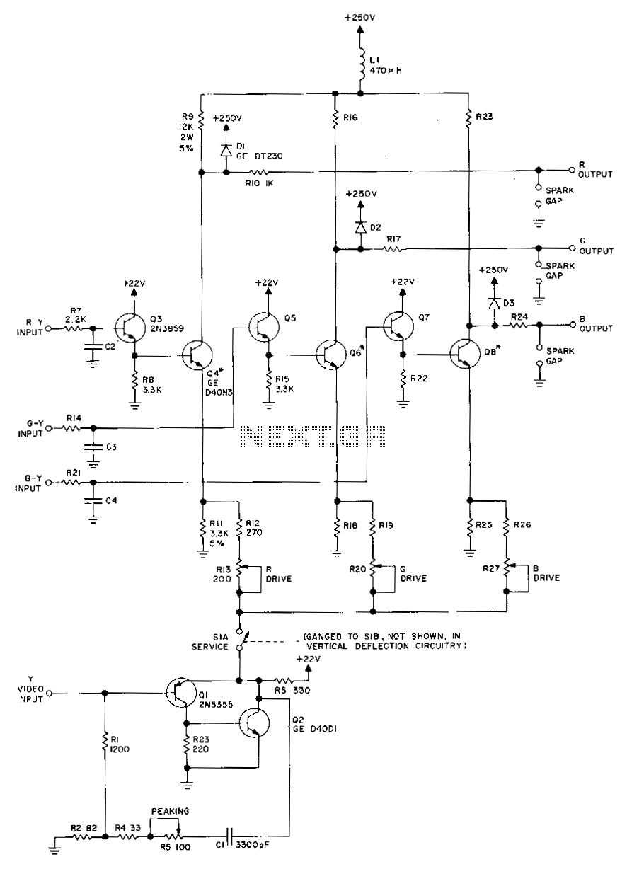
Rgb-video-amplifier
Transistors Q1 and Q2, along with their associated components, provide a low-impedance output necessary for driving the output stages. They enhance gain at high frequencies and improve video peaking for better transient response. Emitter followers Q3, Q5, and Q7 offer...
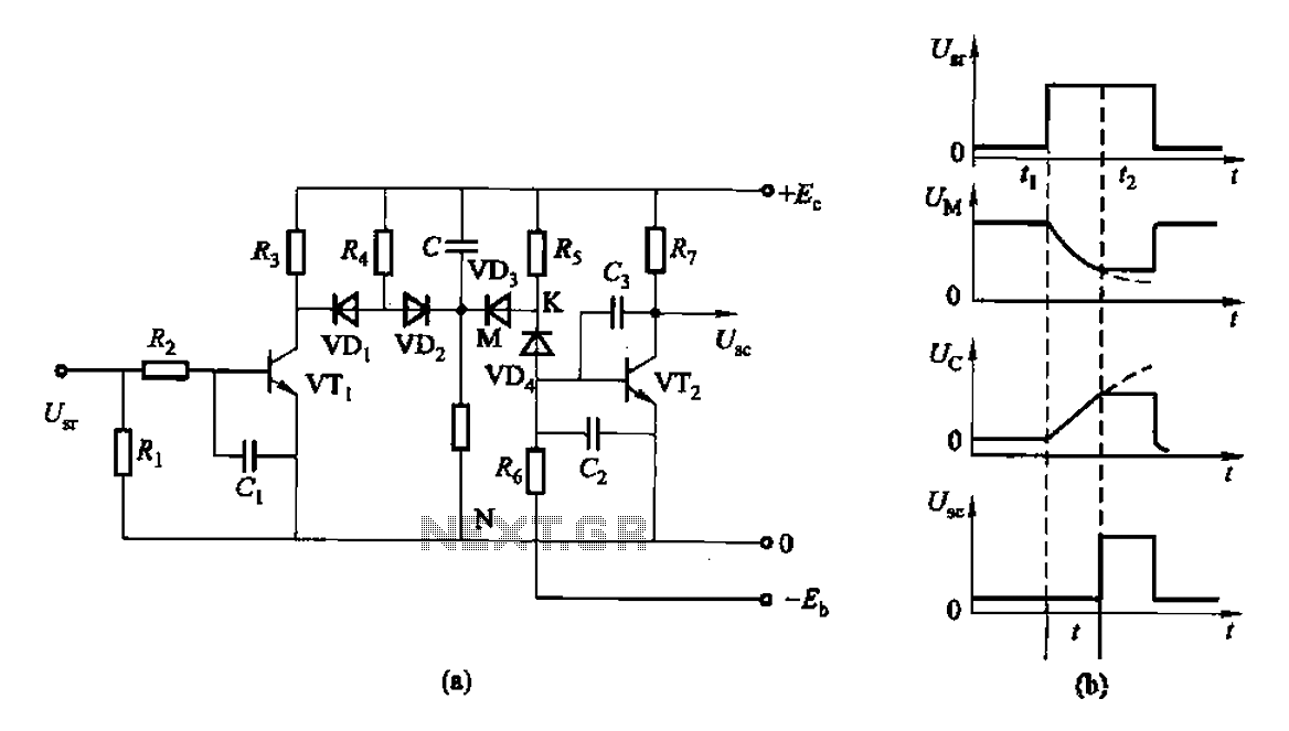
As of control rechargeable delay circuit
This is a control rechargeable delay circuit. Under normal circumstances, when there is no input signal, the transistor VTi is off. VTz is conducting, resulting in a low output potential (U). When a signal is applied, VTi turns on, VTz...
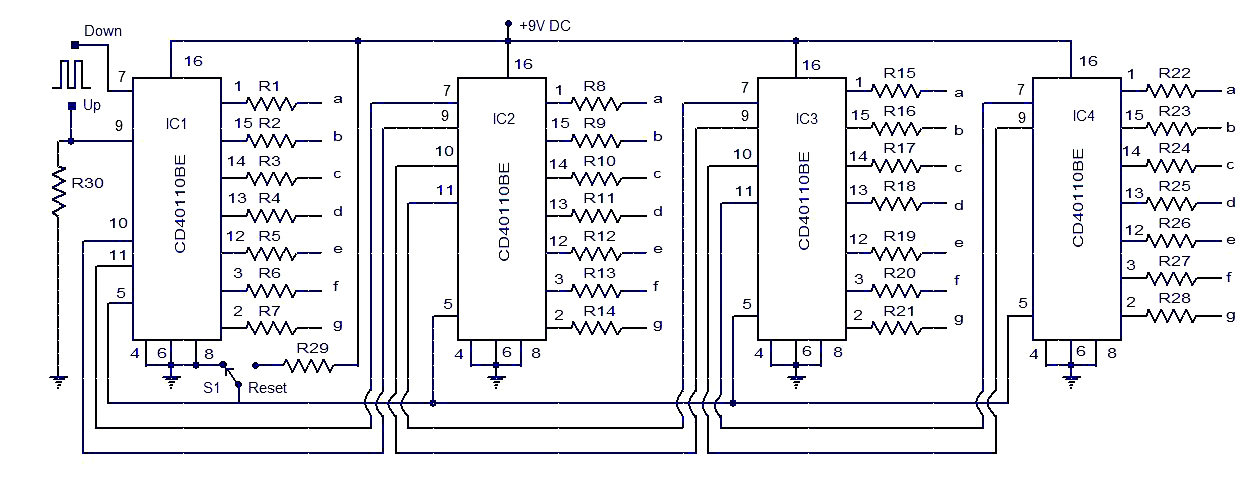
up down counter circuit
This circuit diagram illustrates a simple up/down counter suitable for various applications. It utilizes the CD40110BE IC, a CMOS decade up/down counter. Common cathode seven-segment displays are connected to the outputs of each IC. The display connected to IC1 shows...
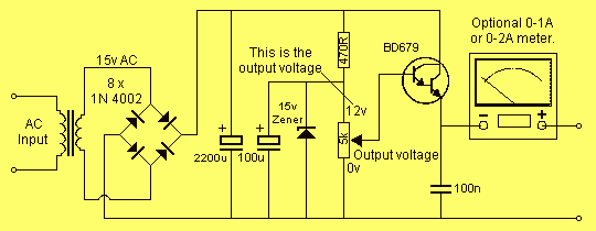
0-12V 2A power supply
This project has two options. It can be a mains operated project, using a 2155 or 2156 transformer or it can be connected to a plug pack. We recommend it be connected to a 16v AC 1 amp plug pack...
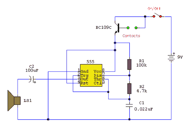
water activated alarm
Under dry conditions, the transistor will not have any bias current and will be completely off. However, when the probes become wet, the transistor will conduct, triggering the alarm. An On/Off switch is included, and it is important to use...
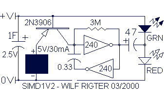
Wilf Rigter`s SIMD1 V2
In the never-ending quest for simplicity, even one extra diode is a price I loathe to pay. To avoid using extra components, it struck me that the two diodes in SIMD1 V1 were connected like the two junctions in one...
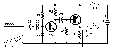
Pulse-Generator & Signal-Tracer
This simple circuit generates narrow pulses at about 700-800Hz frequency. The pulses, containing harmonics up to the MHz region, can be injected into audio or radio-frequency stages of amplifiers, receivers and the like for testing purposes. A high-pitched tone can...
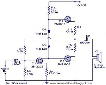
simple audio amplifier
The initial section of the circuit is a preamplifier that utilizes transistor Q1 (2N2222). The collector of transistor Q3 is connected to the base of transistor Q2 (2N2905A), which creates a complementary symmetry pair with Q3 (2N3053). The amplified signal...
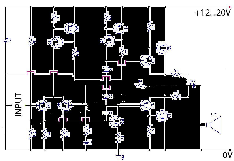
AB Transistor Audio Power Amplifier
This is a Class AB transistor power amplifier. It is straightforward to construct, utilizing standard components, and is known for its stability and reliability. The entire circuit employs commonly available parts and can be easily assembled on a general-purpose board....