


6 Channel Disco Running Lights
#disco lights
#running lights
#triac
#counter
#pulse generator
#transistor
#decorative bulbs
#AC/DC
#sequential lighting
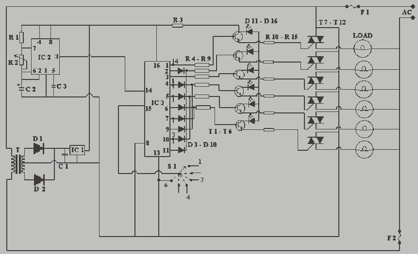
Description: From 230 V AC a DC supply of + 5 V is obtained. The power supply is given to the other blocks. The pulse generator at a particular frequency generates the clock pulses. The clock pulses are counted by a counter and gives output after every 10 pulses. The counter drives the transistors, which form the triac firing circuit. The transistors fire the triacs and they provide sufficient current to the load. Decorative bulbs are connected as load for each triac. The bulbs are sequentially turned ON and OFF in forward and reverse way. The IC 555 works as the pulse generator and feeds the clock pulses to IC 4017. IC 4017 is the heart of this circuit. It works as a counter and gives the output after every 10 pulses. It drives the transistors, which in turn fire the triacs. The triac provides sufficient current to the load.
The circuit described operates by converting 230 V AC into a regulated +5 V DC supply, which powers the various components of the system. The conversion is typically achieved using a transformer to step down the voltage, followed by a rectifier and a voltage regulator to ensure a stable DC output.
The pulse generator, utilizing an IC 555 timer, generates clock pulses at a defined frequency. This IC is configured in astable mode to produce a continuous square wave output, which serves as the timing signal for the subsequent counting operation. The output from the IC 555 is fed into the IC 4017, a decade counter that counts the incoming pulses. The IC 4017 is designed to produce a high output on one of its ten output pins after counting ten clock pulses, allowing for easy sequential control.
The output pins of the IC 4017 are connected to a series of transistors configured as switches. When the IC 4017 activates a transistor, it allows current to flow through the gate of a triac, effectively triggering it. The triac acts as a switch for the load, which in this case consists of decorative bulbs. The triac can handle AC loads and provides sufficient current to light the bulbs.
The sequence in which the bulbs are turned ON and OFF is controlled by the counting mechanism of the IC 4017, which ensures that after every ten pulses, the next bulb in the sequence is activated. This operation can be designed to alternate the bulbs in a forward and reverse manner, creating a visually appealing lighting effect.
In summary, this circuit combines AC to DC conversion, pulse generation, counting, and triac-based switching to achieve a dynamic lighting control system suitable for decorative applications.From 230 V AC a DC supply of + 5 V is obtained. The power supply is given to the other blocks. The pulse generator at a particular frequency generates the clock pulses. The clock pulses are counted by a counter and gives output after every 10 pulses. The counter drives the transistors, which form the triac firing circuit. The transistors fire the triacs and they provide sufficient current to the load. Decorative bulbs are connected as load for each triac. The bulbs are sequentially turned ON and OFF in forward and reverse way. The IC 555 works as the pulse generator and feeds the clock pulses to IC 4017. IC 4017 is the heart of this circuit. It works as a counter and gives the output after every 10 pulses. It drives the transistors, which in turn fire the triacs. The triac provides sufficient current to the load.
The circuit described operates by converting 230 V AC into a regulated +5 V DC supply, which powers the various components of the system. The conversion is typically achieved using a transformer to step down the voltage, followed by a rectifier and a voltage regulator to ensure a stable DC output.
The pulse generator, utilizing an IC 555 timer, generates clock pulses at a defined frequency. This IC is configured in astable mode to produce a continuous square wave output, which serves as the timing signal for the subsequent counting operation. The output from the IC 555 is fed into the IC 4017, a decade counter that counts the incoming pulses. The IC 4017 is designed to produce a high output on one of its ten output pins after counting ten clock pulses, allowing for easy sequential control.
The output pins of the IC 4017 are connected to a series of transistors configured as switches. When the IC 4017 activates a transistor, it allows current to flow through the gate of a triac, effectively triggering it. The triac acts as a switch for the load, which in this case consists of decorative bulbs. The triac can handle AC loads and provides sufficient current to light the bulbs.
The sequence in which the bulbs are turned ON and OFF is controlled by the counting mechanism of the IC 4017, which ensures that after every ten pulses, the next bulb in the sequence is activated. This operation can be designed to alternate the bulbs in a forward and reverse manner, creating a visually appealing lighting effect.
In summary, this circuit combines AC to DC conversion, pulse generation, counting, and triac-based switching to achieve a dynamic lighting control system suitable for decorative applications.From 230 V AC a DC supply of + 5 V is obtained. The power supply is given to the other blocks. The pulse generator at a particular frequency generates the clock pulses. The clock pulses are counted by a counter and gives output after every 10 pulses. The counter drives the transistors, which form the triac firing circuit. The transistors fire the triacs and they provide sufficient current to the load. Decorative bulbs are connected as load for each triac. The bulbs are sequentially turned ON and OFF in forward and reverse way. The IC 555 works as the pulse generator and feeds the clock pulses to IC 4017. IC 4017 is the heart of this circuit. It works as a counter and gives the output after every 10 pulses. It drives the transistors, which in turn fire the triacs. The triac provides sufficient current to the load.
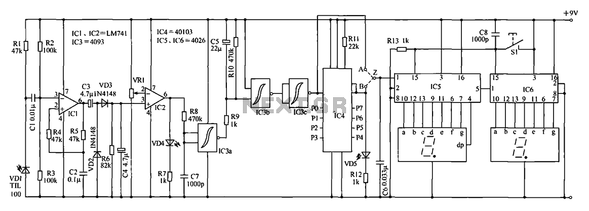
Counter circuit diagram of the digital circuit
The digital counter circuit described utilizes an infrared signal to detect moving targets, making it suitable for counting small devices on a production line as they move along a conveyor belt. This circuit can also be employed for various other...
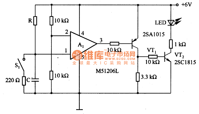
The time delay circuit diagram composed of transistor
The circuit is designed to set a delay time based on the voltage Us and the resistor R. In this configuration, S1 acts as the discharge switch for capacitor C. When switch S1 is closed, the stored charge in capacitor...

Programmable pulse generator
Fast rise and fall times necessitate the utilization of high-speed switching transistors for the differential pair, Q4 and Q5. Linear ramps and sine waves can be produced using the suitable reference input.
The circuit employs high-speed switching transistors, specifically Q4 and...
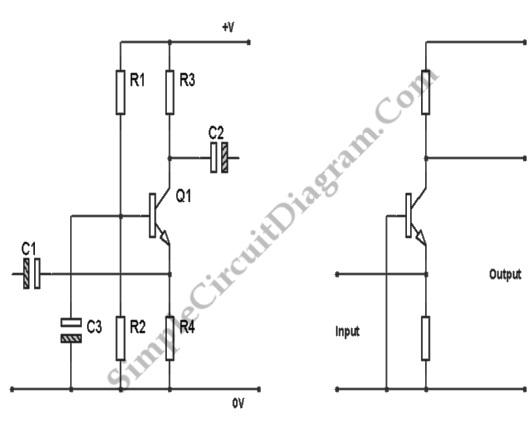
Transistor Common Base Amplifier
In terms of AC signals, the base is connected to the ground through capacitor C3. Consequently, both the input and output are linked to the base, forming a common base amplifier configuration.
The common base amplifier is a type of transistor...
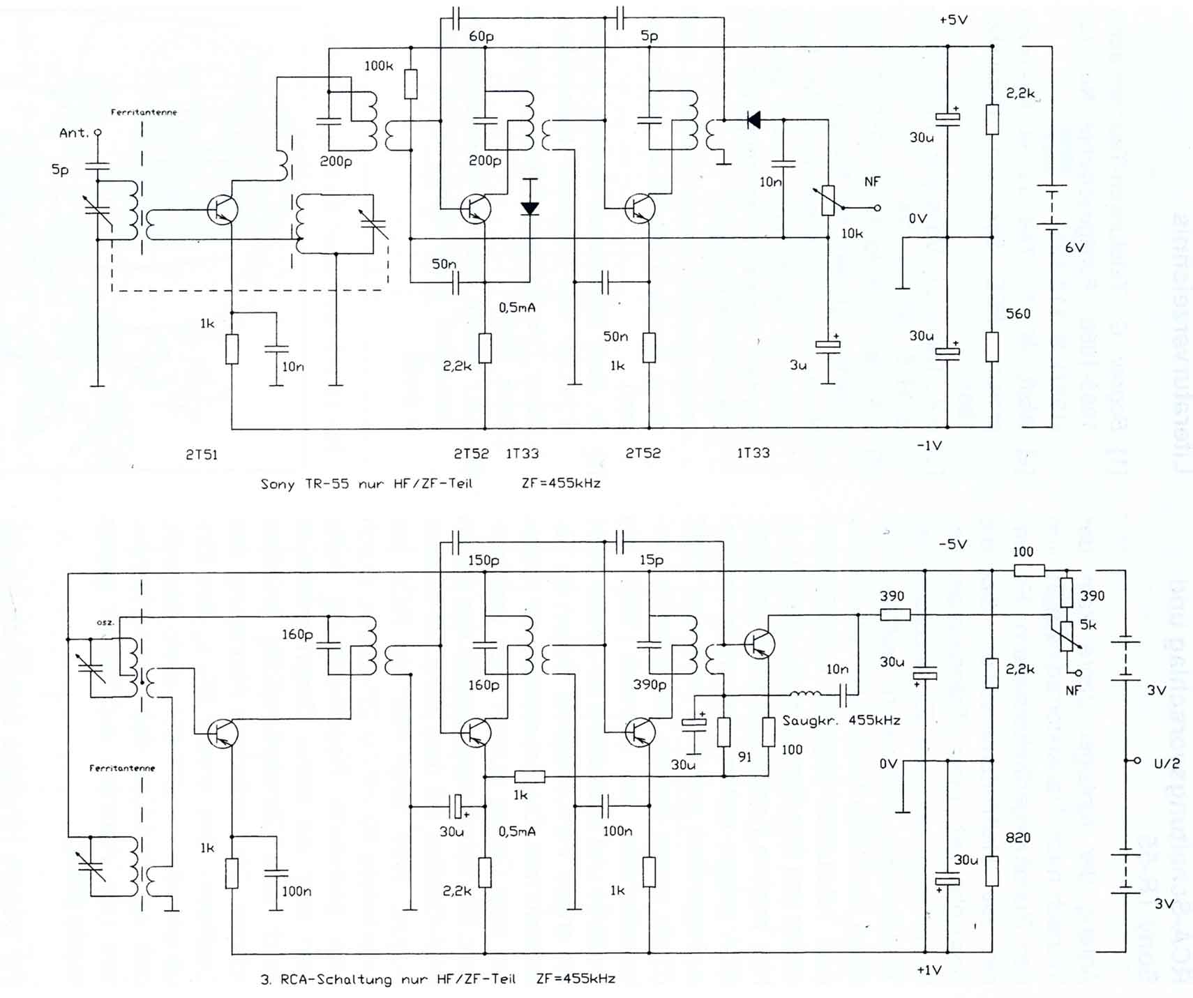
Comments on the Circuits of the first Transistor Radios
The circuitry of the Regency exhibits several unique characteristics. Notable features include the self-oscillating mixer stage, the base bias voltage of the second IF stage derived from the AF power stage, an unusual IF frequency of 262 kHz, and a...
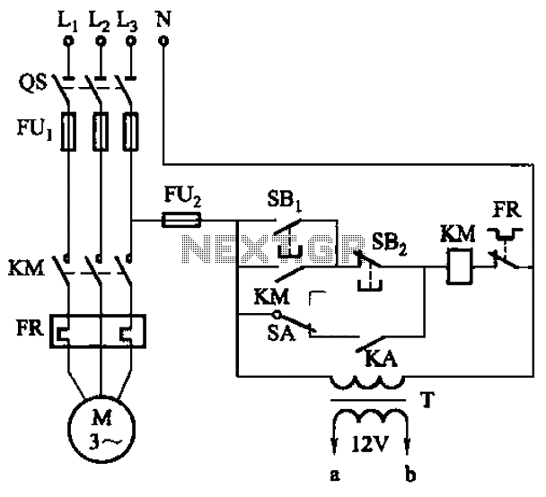
Six a start and stop intermittent cycle control circuits
The circuit illustrated in Figure 3-81 employs a transistor delay circuit to facilitate start-stop cycle control. It can operate in both manual and automatic modes. The circuit is primarily governed by the motor run time circuit, which includes transistors VTi...
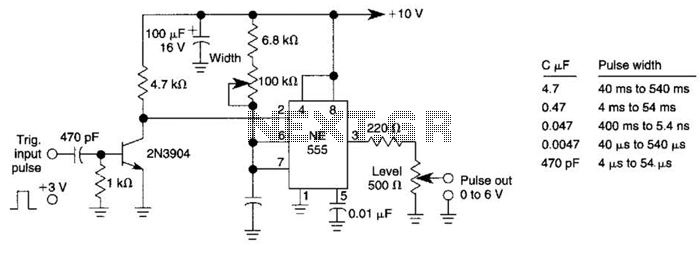
Add-On Pulse Generator Circuit
This pulse generator can enhance a standalone pulse generator. By utilizing a transistor and a 555 timer, it can produce pulse widths ranging from 5 microseconds to 500 microseconds. The value of capacitor C3 can be approximately determined using the...
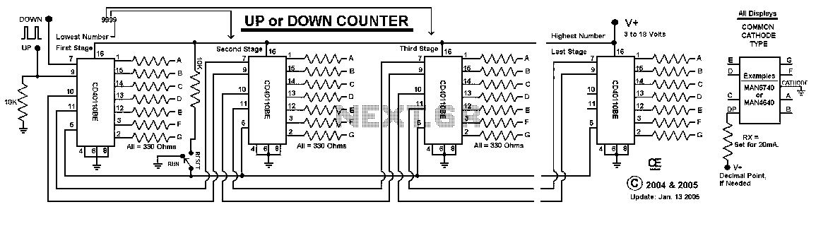
Digital Up / Down Counter
This Circuit uses a CD40110BE, Up/Down Counter IC's. This IC is able to Source Each Segment with 25 mA, Giving a Very Nice Bright Display. The 7 Segment Displays MUST be a Common Cathode Type, as I have used here....
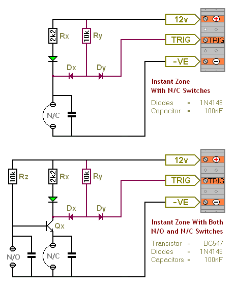
Transistor Based Burglar Alarm - Adding Extra Zones
The Transistor Burglar Alarm System allows for the addition of multiple extra zones. The primary circuit is compatible with standard normally-closed input devices, including magnetic reed contacts, micro switches, foil tape, and passive infrared sensors (PIRs). An auxiliary circuit provides...