


60 LED Clock
#4017 chip
#LED
#clock
#4093 NAND gate
#timer
#digital
#display
#counter
#circuit design
#electronics
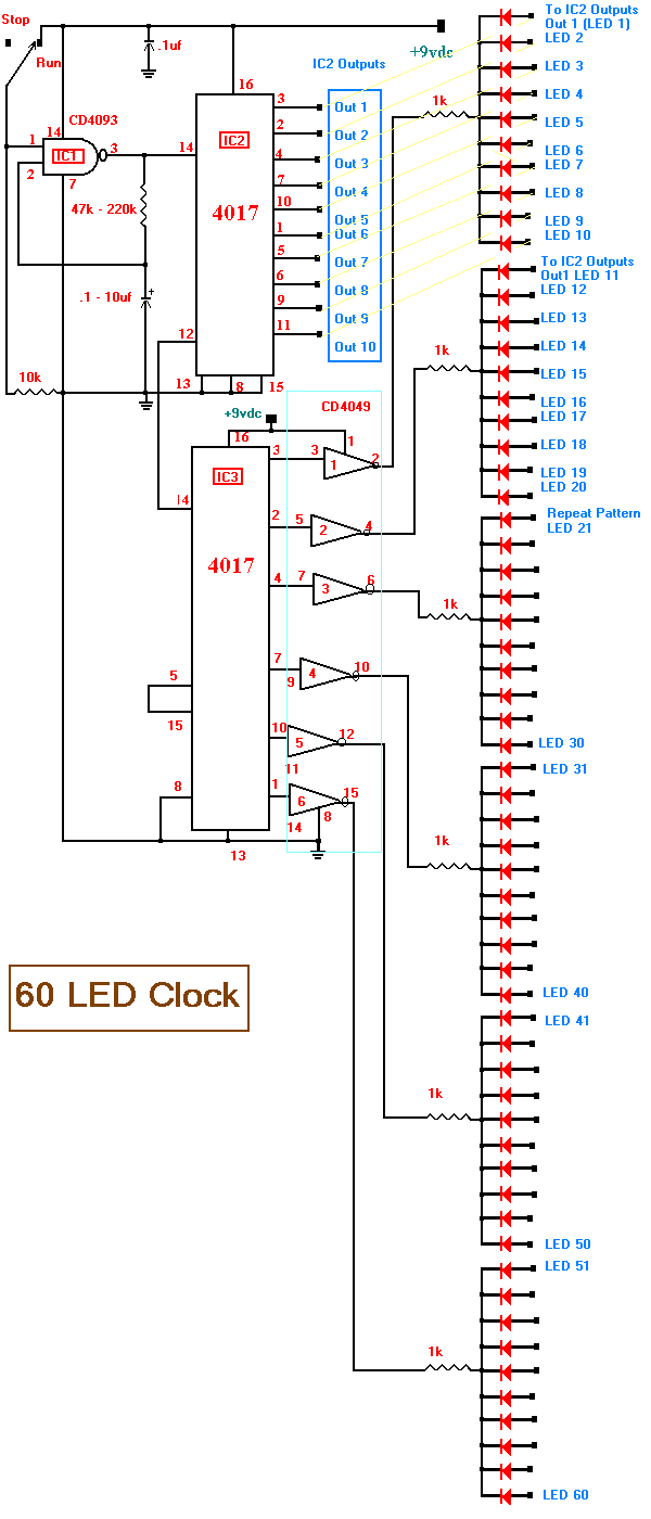
Description: This month's project is based on the 4017 chip that was used in a previous project. It is advisable to review the fundamentals of the 4017 chip as presented in last month's project. The circuit has been modified slightly; for instance, the 4093 NAND gate is now configured to generate clock pulses at exactly one-second intervals. The clock rate is determined by the resistor and capacitor combination connected to the 4093. With a resistor value of 220k ohms and a capacitor value of 4.7µF, the output will yield one-second clock pulses. To increase the clock rate, the values of the resistor or capacitor should be decreased, while increasing these values will decrease the clock rate. It is important to ground all unused pins of the 4093 to prevent noise in the circuit, which could cause the clock to malfunction. Therefore, pins 5, 6, 8, 9, 12, and 13 should be grounded. To operate the circuit, simply switch from the STOP position to the RUN position.
The project focuses on utilizing the CD4017 decade counter, which is a popular integrated circuit for counting applications. It counts from 0 to 10 and can be reset to zero, making it suitable for various timing and sequencing applications. The integration of the 4093 NAND gate serves as an oscillator, producing a clock signal necessary for the operation of the 4017. The clock frequency is crucial for determining how quickly the 4017 progresses through its counting sequence.
The choice of resistor and capacitor values for the 4093 is critical; the RC time constant directly influences the frequency of the output clock pulses. The relationship between the resistor (R) and capacitor (C) can be defined by the formula \( f = \frac{1}{2 \pi R C} \), where \( f \) is the frequency. Thus, a 220k ohm resistor and a 4.7µF capacitor yield a frequency of approximately 0.106 Hz, resulting in a one-second pulse.
Proper grounding of unused pins is essential to ensure stable operation. Noise introduced by floating pins can lead to erratic behavior of the circuit, particularly affecting the clock signal. Grounding the specified pins mitigates this issue, providing a more reliable performance of the 4093 NAND gate.
The operation of the circuit is straightforward. The user can switch between the STOP and RUN positions to control the counting process. In the RUN position, the 4017 will count up with each clock pulse generated by the 4093, while in the STOP position, the counting process halts. This simple yet effective design demonstrates the versatility of the 4017 chip in timing applications, providing an excellent platform for further experimentation and learning in electronics.This months project is based on the 4017 chip that we used in a project last month. If you haven`t had a chance to review the basics of the 4017 chip you may want to review the info presented in June`s project of the month. As you can see see we have changed the circuit a little. For example, the 4093 NAND gate is now set to exactly 1 second clock pulses. The clock rate is determined by the resistor and capacitor combination on the 4093. If the resistor is 220k ohms and the capacitor is 4. 7uf then the output will be 1 second clock pulses. To increase the clock rate you should decrease the value of the resistor or capacitor. To decrease the clock rate you should increase the value of the resistor or capacitor. Please remember to ground all unused legs of the 4093 or noise in the circuit will occur and cause the clock to malfunction. Therefore, ground pins 5, 6, 8, 9, 12, and 13. To operate the circuit simply move the switch from STOP to RUN. We aim to transmit more information by carrying articles. Please send us an E-mail to wanghuali@hqew. net within 15 days if we are involved in the problems of article content, copyright or other problems.
We will delete it soon.
The project focuses on utilizing the CD4017 decade counter, which is a popular integrated circuit for counting applications. It counts from 0 to 10 and can be reset to zero, making it suitable for various timing and sequencing applications. The integration of the 4093 NAND gate serves as an oscillator, producing a clock signal necessary for the operation of the 4017. The clock frequency is crucial for determining how quickly the 4017 progresses through its counting sequence.
The choice of resistor and capacitor values for the 4093 is critical; the RC time constant directly influences the frequency of the output clock pulses. The relationship between the resistor (R) and capacitor (C) can be defined by the formula \( f = \frac{1}{2 \pi R C} \), where \( f \) is the frequency. Thus, a 220k ohm resistor and a 4.7µF capacitor yield a frequency of approximately 0.106 Hz, resulting in a one-second pulse.
Proper grounding of unused pins is essential to ensure stable operation. Noise introduced by floating pins can lead to erratic behavior of the circuit, particularly affecting the clock signal. Grounding the specified pins mitigates this issue, providing a more reliable performance of the 4093 NAND gate.
The operation of the circuit is straightforward. The user can switch between the STOP and RUN positions to control the counting process. In the RUN position, the 4017 will count up with each clock pulse generated by the 4093, while in the STOP position, the counting process halts. This simple yet effective design demonstrates the versatility of the 4017 chip in timing applications, providing an excellent platform for further experimentation and learning in electronics.This months project is based on the 4017 chip that we used in a project last month. If you haven`t had a chance to review the basics of the 4017 chip you may want to review the info presented in June`s project of the month. As you can see see we have changed the circuit a little. For example, the 4093 NAND gate is now set to exactly 1 second clock pulses. The clock rate is determined by the resistor and capacitor combination on the 4093. If the resistor is 220k ohms and the capacitor is 4. 7uf then the output will be 1 second clock pulses. To increase the clock rate you should decrease the value of the resistor or capacitor. To decrease the clock rate you should increase the value of the resistor or capacitor. Please remember to ground all unused legs of the 4093 or noise in the circuit will occur and cause the clock to malfunction. Therefore, ground pins 5, 6, 8, 9, 12, and 13. To operate the circuit simply move the switch from STOP to RUN. We aim to transmit more information by carrying articles. Please send us an E-mail to wanghuali@hqew. net within 15 days if we are involved in the problems of article content, copyright or other problems.
We will delete it soon.
Regulated LED Lamp
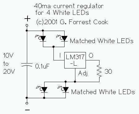
The LM317L and resistor act as a current regulator set to 40ma. Current flows from the battery through one pair of LEDs, through the regulator, through the other pair of LEDs, and back to the battery. The capacitor filters out...
Two-LED Pilot Light
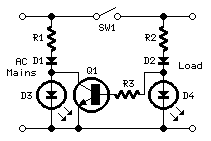
This circuit was designed on request and can be useful to those wishing to have, say, a red LED illuminated when an appliance is on and a green LED illuminated when the same appliance is off. Any mains operated appliance...
BarGraph Ccts
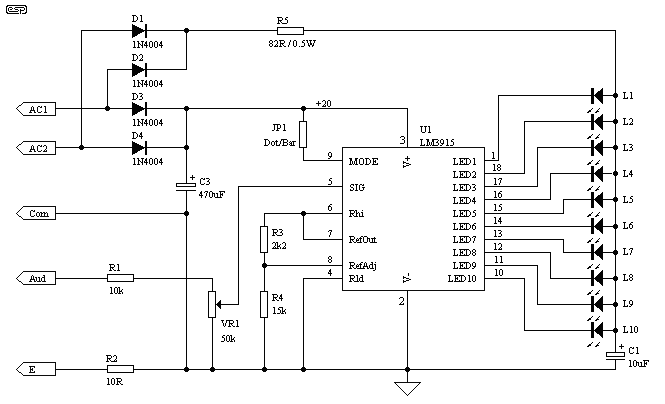
The LED meter is simpler and smaller than its analog counterpart and is commonly found in audio equipment. This version utilizes a National Semiconductor integrated circuit (IC) and employs a logarithmic scale. Each LED operates with a 3 dB difference...
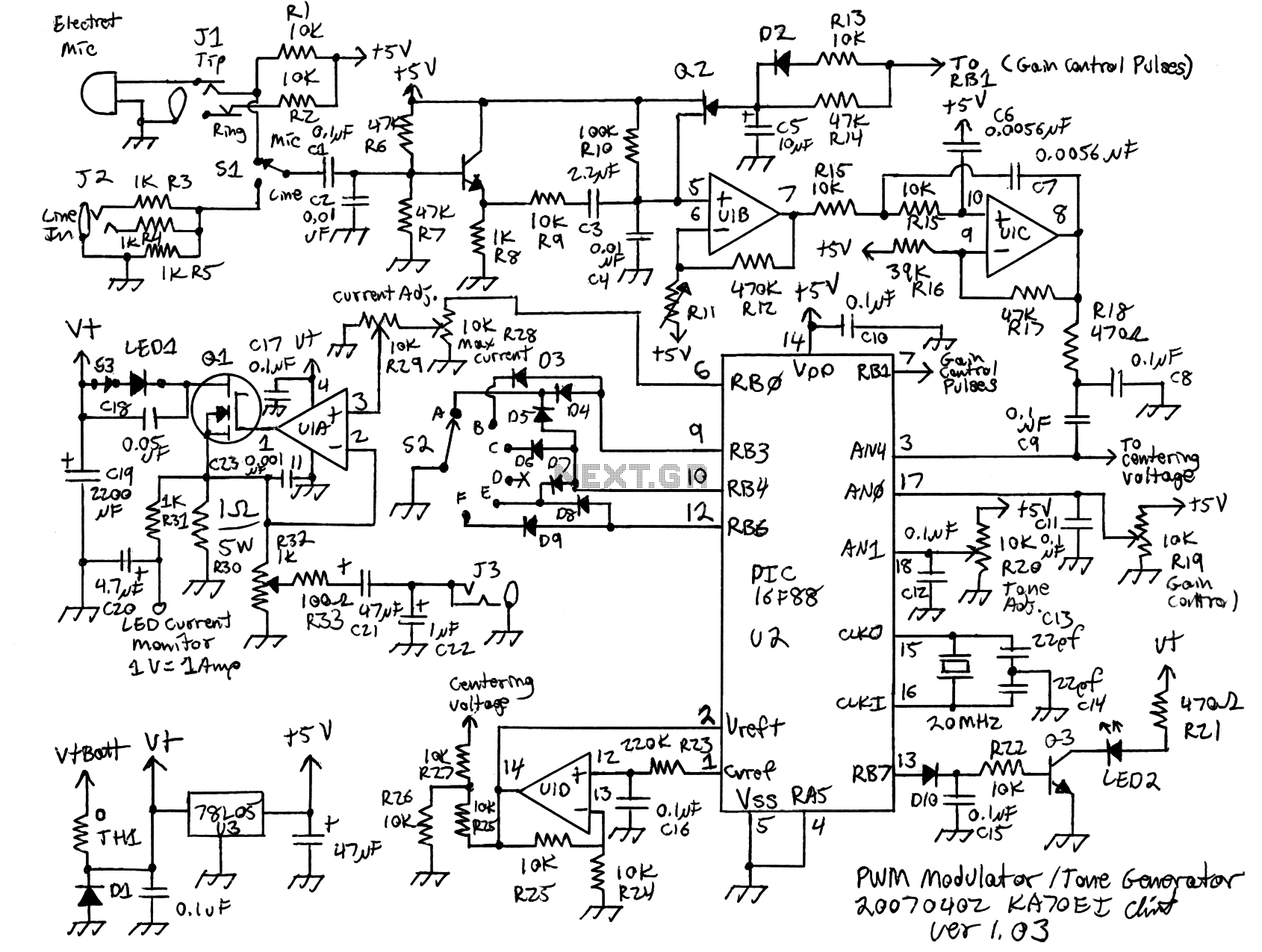
LED pulse width modulator
Early in the exploration of high-power LEDs, such as the Luxeon 1 and 3-watt devices, the potential of Pulse Width Modulation (PWM) techniques for LED modulation was considered. This method theoretically minimizes distortion by making the LED's "Current versus Luminous...
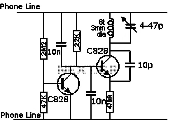
The Time Delay Circuit
The duration for which the circuit remains active is determined by the time required for the stored electrical current to leak back into the circuit, which keeps the transistor and the entire circuit energized. A resistor is present that limits...
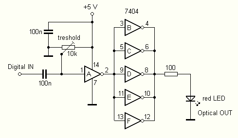
LED output from SB Live! Value
Many modern audio recorders are now compatible with digital input S/PDIF (Sony/Philips Digital Interface). Devices like CD changers, MiniDisc recorders, computer sound cards, and the like work with digital signals using the S/PDIF protocol. This digital connection between two devices,...
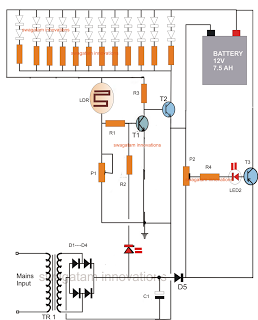
LED Emergency Light Circuit With Battery Over Charge Protection
The following circuit is an LED emergency light circuit featuring advanced functionalities such as overcharge battery cut-off, daytime auto-disable, and automatic activation of the LEDs during AC mains failure, reverting to charging mode when power is restored. The circuit employs...
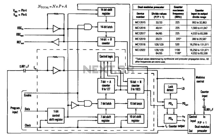
1Ghz Divide-By-N Counter
Counter speeds for CMOS and TTL programmable counters are limited to under 100 MHz. ECL-type devices can approach a few hundred MHz but require significant current. However, using the dual-modulus-prescaling technique in conjunction with phase-locked-loop synthesizer chips that control the...
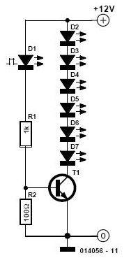
led flashing circuit
Its state is constantly changing, and this change affects the flow of current and voltage, which is visible with the two LEDs. The speed of the LED flasher can be adjusted with potentiometer P1. As an astable multivibrator, the circuit...