


A Better Shade of Green
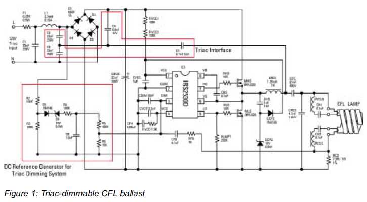
Description: A simple yet versatile dimming-ballast solution for low-energy lighting. EU-wide legislation promoting the use of compact fluorescent lamps (CFLs) in place of incandescent bulbs could save significant energy.
The proposed dimming-ballast solution is designed to enhance the efficiency and functionality of compact fluorescent lamps (CFLs) in various lighting applications. This system enables users to adjust the brightness of CFLs, providing flexibility for different environments and reducing energy consumption.
The circuit typically includes a dimmer switch, which can be either a resistive or electronic type, and a ballast that regulates the current flowing through the CFL. The electronic ballast is preferred for its higher efficiency and ability to provide a flicker-free light output.
The dimming mechanism can be implemented using a phase-cut dimming technique, which either cuts the leading or trailing edge of the AC waveform, effectively reducing the power delivered to the lamp. This method allows for smooth dimming capabilities while maintaining the integrity of the CFL’s operation.
In addition, the circuit may incorporate feedback mechanisms to monitor the lamp's performance and adjust the ballast's output accordingly, ensuring optimal operation across various dimming levels. Safety features, such as overcurrent protection and thermal management, should also be integrated to prevent overheating and ensure longevity.
Overall, this dimming-ballast solution not only complies with energy regulations but also enhances user experience by allowing for customizable lighting options in residential and commercial spaces.A Simple yet Versatile Dimming-Ballast Solution for Low-Energy Lighting EU-wide legislation promoting use of Compact Fluorescent lamps (CFLs) in place of incandescent bulbs could save as much..
The proposed dimming-ballast solution is designed to enhance the efficiency and functionality of compact fluorescent lamps (CFLs) in various lighting applications. This system enables users to adjust the brightness of CFLs, providing flexibility for different environments and reducing energy consumption.
The circuit typically includes a dimmer switch, which can be either a resistive or electronic type, and a ballast that regulates the current flowing through the CFL. The electronic ballast is preferred for its higher efficiency and ability to provide a flicker-free light output.
The dimming mechanism can be implemented using a phase-cut dimming technique, which either cuts the leading or trailing edge of the AC waveform, effectively reducing the power delivered to the lamp. This method allows for smooth dimming capabilities while maintaining the integrity of the CFL’s operation.
In addition, the circuit may incorporate feedback mechanisms to monitor the lamp's performance and adjust the ballast's output accordingly, ensuring optimal operation across various dimming levels. Safety features, such as overcurrent protection and thermal management, should also be integrated to prevent overheating and ensure longevity.
Overall, this dimming-ballast solution not only complies with energy regulations but also enhances user experience by allowing for customizable lighting options in residential and commercial spaces.A Simple yet Versatile Dimming-Ballast Solution for Low-Energy Lighting EU-wide legislation promoting use of Compact Fluorescent lamps (CFLs) in place of incandescent bulbs could save as much..
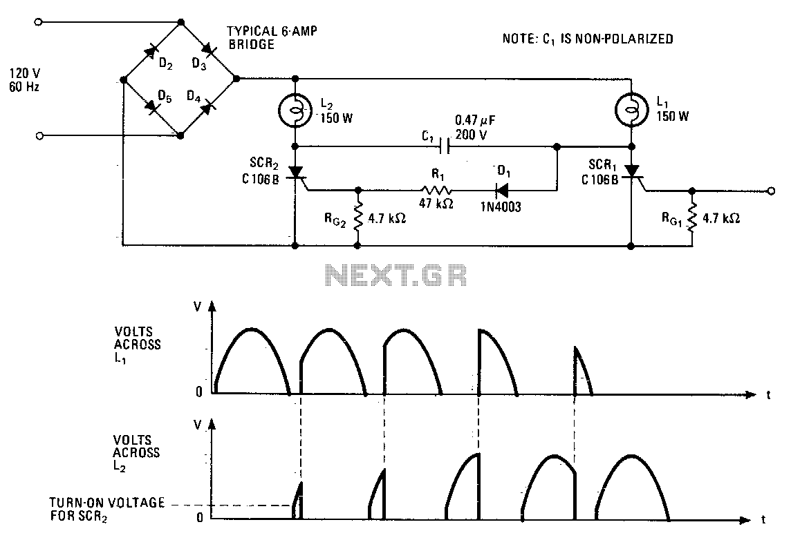
Complementary lighting control
This lighting control unit will gradually decrease the brightness of one lamp while simultaneously increasing the brightness of another. The two loads maintain precise tracking without the need for manual adjustments. The gate of SCR1, a silicon-controlled rectifier, is activated...
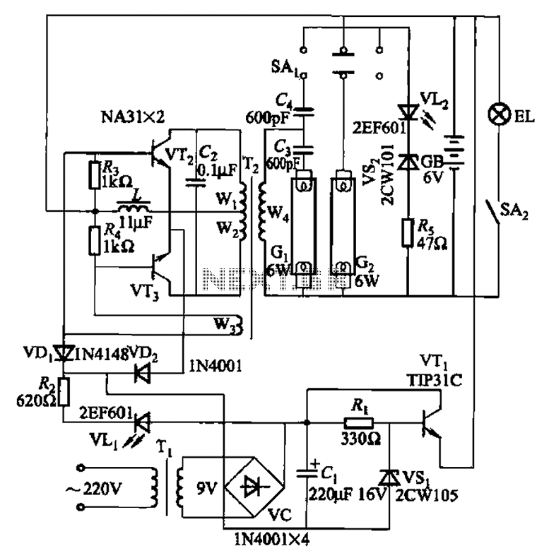
Double tube fluorescent emergency circuit 2
This is a Nissan Panasonic rechargeable emergency fluorescent lamp circuit. It features built-in 6V, 4Ah high-energy batteries that can be directly charged. The circuit supports two 6W fluorescent lamps. It includes functional switches SAi and SAz. When SAi is set...
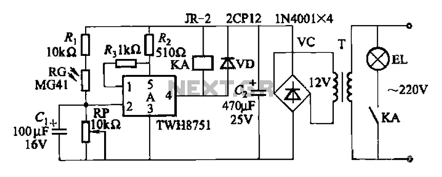
Twelve road lighting control circuits
The adjustment potentiometer RP can modify the sensitivity of the device. Capacitors C1 function as an anti-light interference mechanism for instantaneous action.
The adjustment potentiometer (RP) is a variable resistor that allows for fine-tuning of the device's sensitivity. By altering the...
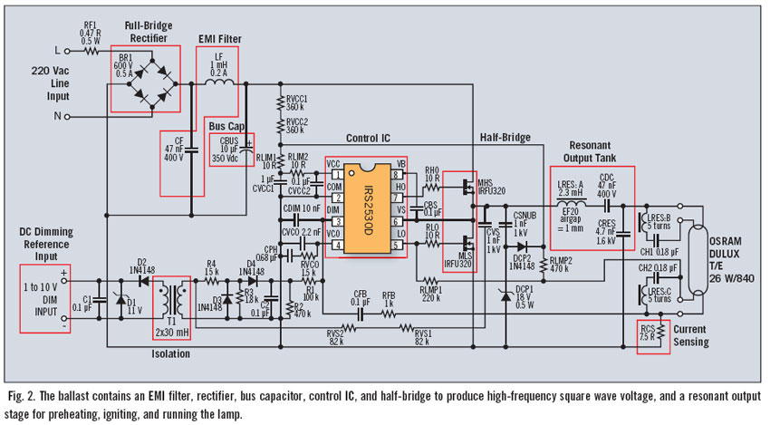
simple yet versatile dimming ballast solution
Fluorescent dimming systems can enhance visual comfort and lower utility costs through strategies such as daylight harvesting, demand reduction, and scheduled dimming. A dimming electronic ballast plays a crucial role in this system. To execute dimming functions, the ballast must...
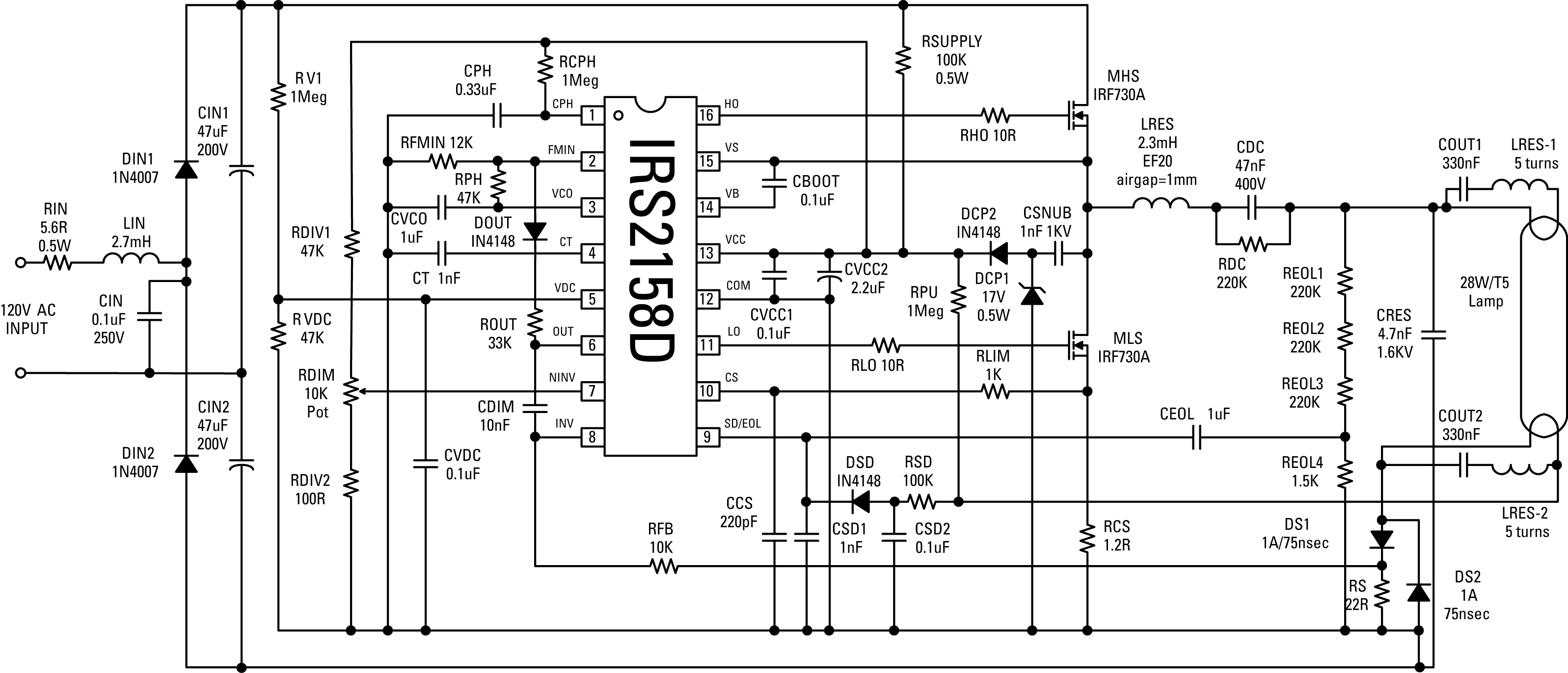
IC fluorescent dimming considerations
This article presents an overview of fluorescent dimming and an application circuit for low-end small fixture applications ICs, where dimming levels below 10% are required alongside comprehensive protection features. The electronic ballast circuit block diagram includes the AC line input...
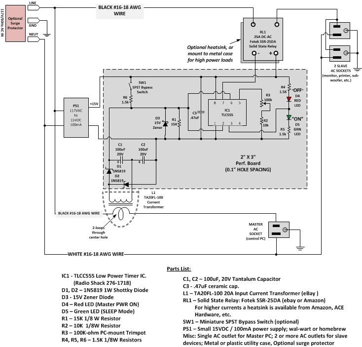
eliminate wasted phantom power
Most Apple and Windows PCs can enter "sleep" or "standby" mode when not in use instead of being completely shut down. This mode allows the operating system to restore all previous work sessions within seconds upon waking via keyboard or...
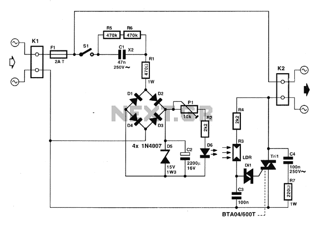
Lighting auto controller
The following governor is designed to regulate the light intensity of a 220 V incandescent lamp. The circuit consists of relatively few components, allowing for easy assembly on a small circuit board. It is recommended to enclose the completed assembly...
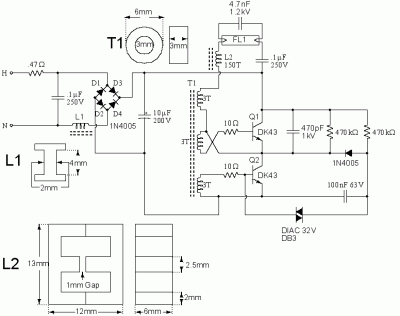
14 Watt Compact Fluorescent Electronic Ballast
The following circuit illustrates a 14 Watt Compact Fluorescent Electronic Ballast Circuit Diagram. Features: it is similar to a 16 Watt circuit, 14 Watt.
The 14 Watt Compact Fluorescent Electronic Ballast Circuit is designed to efficiently drive compact fluorescent lamps (CFLs)...
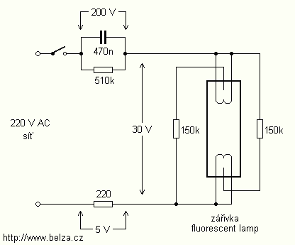
Energy Saving Night Light circuit
The lamps are usually used as ballast or electronic ballast inverter. Here it is used to reduce voltage capacitor reactance. Interesting is also the method of ignition of the auxiliary electrodes involved over 150 Ohm resistors. To start simply involve...