


AC 220 Volts Flashing Lamps Circuit
#flashing lamps
#SCR
#timing circuit
#Christmas tree lights
#AC 220V
#transistor
#resistors
#capacitor
#frequency adjustment
#holiday lighting
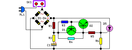
Description: This circuit serves as a dependable alternative to thermally-activated switches designed for flashing Christmas tree lamps. The arrangement consisting of Q1, Q2, and associated resistors activates the silicon-controlled rectifier (SCR). The timing function is determined by resistors R1, R2, and capacitor C1. To adjust the flashing frequency, it is advised not to alter the values of R1 and R2; instead, modify the capacitance of C1 within the range of 100 to 2200 µF.
This circuit utilizes a combination of transistors (Q1 and Q2) and resistors to control the operation of an SCR, which is pivotal in managing the power delivered to the lamp. The transistors are configured to form a trigger circuit that activates the SCR when a specific voltage level is reached. The resistors R1 and R2, along with capacitor C1, form an RC timing circuit that dictates the frequency of the flashing lamps.
The timing capacitor C1 plays a crucial role in determining how long the SCR remains conductive during each cycle. By varying the capacitance of C1, the time constant of the RC circuit changes, thus altering the frequency of the flashing effect. It is essential to maintain the values of R1 and R2 constant to ensure stable operation, as they set the thresholds for the triggering mechanism of the transistors.
In practical applications, the circuit can be powered by a standard AC supply, and the SCR can handle the load of the Christmas tree lamps efficiently. The design ensures that the flashing effect is visually appealing and can be adjusted to suit different aesthetic preferences by simply changing the capacitor value. This makes it an ideal solution for holiday lighting applications where reliability and ease of use are paramount. Proper heat dissipation measures should also be considered to ensure the longevity of the components involved, particularly the SCR, which can generate heat during operation.This circuit is intended as a reliable replacement to thermally-activated switches used for Christmas tree lamp-flashing. The device formed by Q1, Q2 and related resistors triggers the SCR. Timing is provided by R1, R2 & C1. To change flashing frequency do not modify R1 and R2 values: set C1 value from 100 to 2200µF instead..
This circuit utilizes a combination of transistors (Q1 and Q2) and resistors to control the operation of an SCR, which is pivotal in managing the power delivered to the lamp. The transistors are configured to form a trigger circuit that activates the SCR when a specific voltage level is reached. The resistors R1 and R2, along with capacitor C1, form an RC timing circuit that dictates the frequency of the flashing lamps.
The timing capacitor C1 plays a crucial role in determining how long the SCR remains conductive during each cycle. By varying the capacitance of C1, the time constant of the RC circuit changes, thus altering the frequency of the flashing effect. It is essential to maintain the values of R1 and R2 constant to ensure stable operation, as they set the thresholds for the triggering mechanism of the transistors.
In practical applications, the circuit can be powered by a standard AC supply, and the SCR can handle the load of the Christmas tree lamps efficiently. The design ensures that the flashing effect is visually appealing and can be adjusted to suit different aesthetic preferences by simply changing the capacitor value. This makes it an ideal solution for holiday lighting applications where reliability and ease of use are paramount. Proper heat dissipation measures should also be considered to ensure the longevity of the components involved, particularly the SCR, which can generate heat during operation.This circuit is intended as a reliable replacement to thermally-activated switches used for Christmas tree lamp-flashing. The device formed by Q1, Q2 and related resistors triggers the SCR. Timing is provided by R1, R2 & C1. To change flashing frequency do not modify R1 and R2 values: set C1 value from 100 to 2200µF instead..
Purpose of SCRs in Power Factor Circuit
A Power Factor Correction (PFC) board has been obtained from an old Sun Microsystems Spark450 power supply (part number 300-1359-xx). This board contains all necessary components for a 650-watt inverter. However, the complete PFC circuit is not fully detailed in...
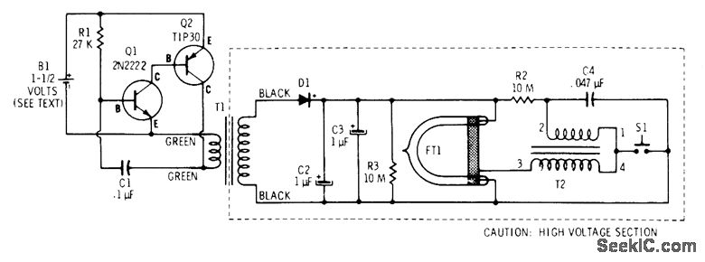
XENON STROBE
A two-transistor oscillator generates pulses at approximately 500 Hz to step up the voltage using a 300-mA filament transformer (T1, Radio Shack 273-1384) for charging storage capacitors C2 and C3, which are 250-V electrolytics. At the same time, capacitor C4...
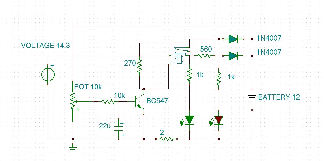
modified battery charger circuit
Using a transistor will not yield accurate results, and the adjustment process can become quite tedious. The circuit is technically correct; if the tripping point can be adjusted properly, it may function as intended. Vinod states that he created a...
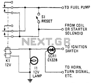
Auto Ignition Cut-Off
This circuit utilizes a combination of a silicon-controlled rectifier (SCR) and a relay to interrupt the ignition system unless a positive voltage is applied to the gate of the SCR. This configuration serves as an anti-theft device, as the vehicle...
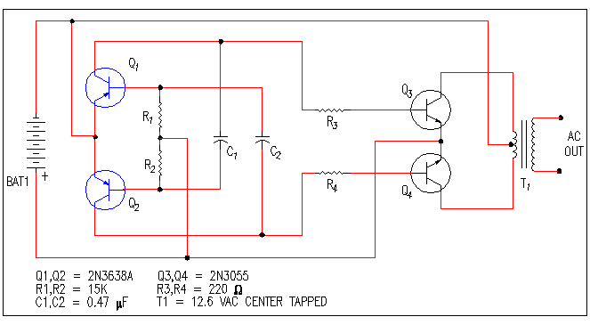
Inverter Schematics
A small bias on the bases of Q1 and Q2 through R1 and R2 assists in initiating the circuit. This provides each transistor's base with a slight forward bias, enabling both transistors to conduct when the circuit is initially powered...
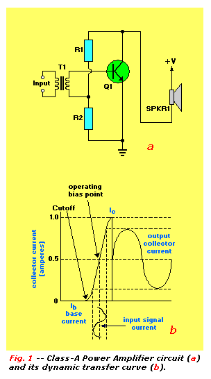
Transistor Tutorial Power Amplifiers Part 4
An audio power amplifier can enhance weak signals from devices like tuners, CD players, or tape decks to fill a room with sound. This article emphasizes the operating principles and circuitry of low-frequency power amplifiers utilizing bipolar junction transistors (BJTs)....
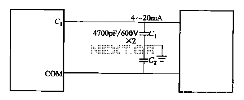
Control cables plus anti-interference capacitors
A capacitor filter is utilized in frequency control circuits and is a common method for implementing anti-jamming measures. It addresses frequency interference noise within the wiring of the 4-20mA control loop. The anti-interference is achieved through bypass capacitors C1 and...
The Transistor Amplifier-P2
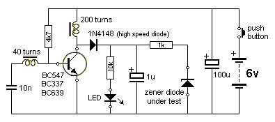
The three circuits described provide a constant current to the LED (or LEDs) when the supply voltage reaches 15V or higher. The second and third circuits can be activated or deactivated through the input line by turning on the top...
Simple Audio amplifier Using Transistors
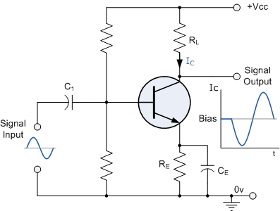
Construct a basic audio amplifier utilizing transistors. While integrated circuit (IC) designs are available for this purpose, the intention is to use transistors to gain practical knowledge about their amplification capabilities. The article "Amplifier Basics - How Amps Work (Intro)"...