


Ac-flasher
#AC-flasher
#lamp
#flashing rate
#resistor
#capacitor
#light control
#timing circuit
#10-KO resistor
#50-mF capacitor
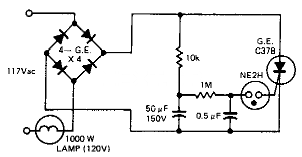
Description: The circuit is capable of flashing a large lamp. The flashing rate is determined by a 10 kΩ resistor and a 50 µF capacitor. Increasing or decreasing the value of the capacitor has a corresponding effect on the flash rate.
The circuit operates as a simple astable multivibrator, utilizing a resistor-capacitor (RC) timing network to generate a periodic flashing effect for the lamp. The key components include a 10 kΩ resistor and a 50 µF capacitor, which together establish the time constant of the circuit.
The flashing rate, or frequency, of the lamp is inversely related to the capacitance value. As the capacitance increases, the time taken to charge and discharge the capacitor also increases, leading to a slower flashing rate. Conversely, reducing the capacitance results in a quicker charge and discharge cycle, thus increasing the flashing rate.
The circuit can be further enhanced by incorporating a transistor to drive the large lamp, allowing for higher current handling capabilities. This can be achieved by connecting the output of the timing circuit to the base of an NPN transistor, which in turn can control the current flowing through the lamp.
In practical applications, the circuit may also include additional components such as diodes for flyback protection if an inductive load is used, or additional resistors for fine-tuning the flashing rate. Furthermore, the use of a variable resistor in place of the fixed 10 kΩ resistor can allow for adjustable flashing rates, offering flexibility in design for various applications.
Overall, this simple yet effective circuit design provides a reliable method for creating a flashing effect in large lamps, suitable for decorative lighting, signaling, or alert systems.is capable of flashing a large lamp. Flashing rate is determined by the 10-KO resistor and the 50-mF capacitor. Increasing or decreasing the value of the capacitor has a corresponding effect on the flash rate.
The circuit operates as a simple astable multivibrator, utilizing a resistor-capacitor (RC) timing network to generate a periodic flashing effect for the lamp. The key components include a 10 kΩ resistor and a 50 µF capacitor, which together establish the time constant of the circuit.
The flashing rate, or frequency, of the lamp is inversely related to the capacitance value. As the capacitance increases, the time taken to charge and discharge the capacitor also increases, leading to a slower flashing rate. Conversely, reducing the capacitance results in a quicker charge and discharge cycle, thus increasing the flashing rate.
The circuit can be further enhanced by incorporating a transistor to drive the large lamp, allowing for higher current handling capabilities. This can be achieved by connecting the output of the timing circuit to the base of an NPN transistor, which in turn can control the current flowing through the lamp.
In practical applications, the circuit may also include additional components such as diodes for flyback protection if an inductive load is used, or additional resistors for fine-tuning the flashing rate. Furthermore, the use of a variable resistor in place of the fixed 10 kΩ resistor can allow for adjustable flashing rates, offering flexibility in design for various applications.
Overall, this simple yet effective circuit design provides a reliable method for creating a flashing effect in large lamps, suitable for decorative lighting, signaling, or alert systems.is capable of flashing a large lamp. Flashing rate is determined by the 10-KO resistor and the 50-mF capacitor. Increasing or decreasing the value of the capacitor has a corresponding effect on the flash rate.
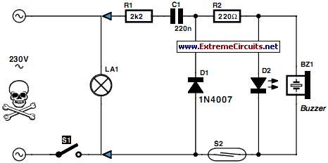
Put That Light Out
If the light in a seldom-used room, such as a loft, is forgotten and left on, it can remain illuminated for extended periods, leading to significant electricity costs. To address this issue, electronics enthusiasts can design a simple circuit to...
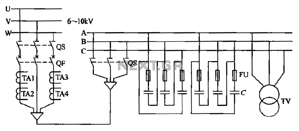
High-pressure centralized compensation capacitor circuit
The compensation system is designed to focus on a high-pressure, high-voltage capacitor bank installed in the substation 6-10 kV bus. Compensation can only be implemented in this manner for the 6-10 kV bus before the reactive power on the line,...
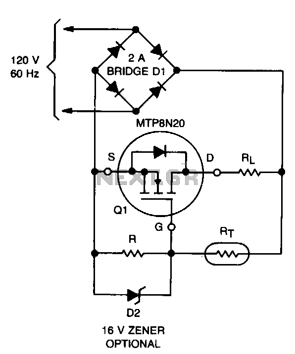
Lamp-life-extender
The lifespan of a lamp can be prolonged by enhancing the conditions under which its filament operates. This involves eliminating the inrush overcurrent surge and reducing the mechanical stress (vibration) on the filament caused by an AC source. The circuit...
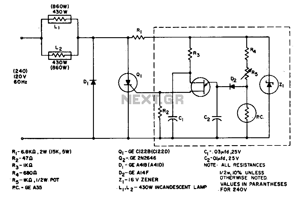
860 Watt limited-range light control
The system is designed to regulate an 860-watt lamp load from half to full power. This is achieved through the controlled half-plus-fixed half-wave phase control method. Applying half power to an incandescent lamp results in 30% of the full light...
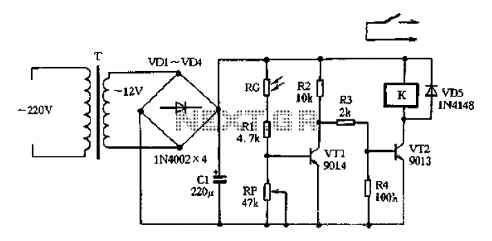
Light control relay control lamp
The circuit operates on 220V AC input, which is transformed to approximately 12V DC using a step-down transformer (T), a diode bridge rectifier (VDI-VD4), and a filter capacitor (C1). This setup is designed to power the entire circuit. The light...
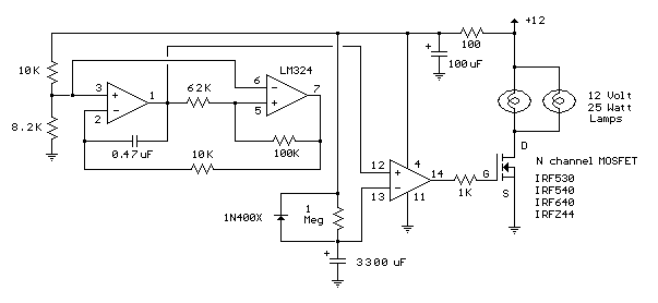
Lamp Fader schematic
The sunset lamp comes on at full brightness and then slowly fades out over 1.5 hours time and stays off until power is recycled. More: You can use 12 Volt 25 Watt lamps.
The described sunset lamp operates on a 12...
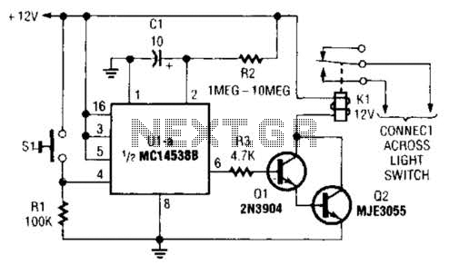
Lamp-Switching Circuit Circuit
A normally open pushbutton switch (SI) provides a positive input pulse to pin 4 of U1, activating the integrated circuit (IC). The output from U1 at pin 6 delivers base-drive current to a Darlington pair consisting of Q1 and Q2,...
ELF MONITOR
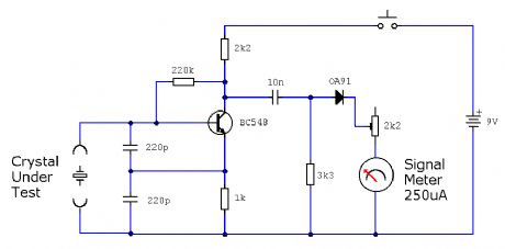
The capacitor instrument is not intended for measuring the capacitance of capacitors; rather, it is designed to identify whether a capacitor is functional or defective, as well as to detect short circuits or open circuits. This functionality provides reliable quality...
3-Way Light Control
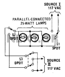
This hookup is useful in certain house wiring situations where only two wires are available between switches, rather than the usual three-way setup that requires three wires. SI and S2 are standard three-way switches, while S3, a double-pole double-throw (DPDT)...