


advanced bicycle lighting Schematic
#bicycle lighting
#NiCd batteries
#battery charger
#automated
#LED
#power supply
#energy efficient
#safety
#cycling
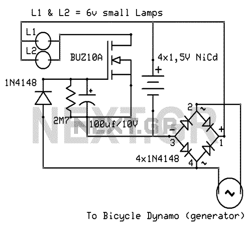
Description: That Circuit is an advanced bicycle lighting system which will power your lights and also charge four NiCd batteries while you running in the streets, for keeping the lights on while the bicycle is stopped. Its fully automated without any switches. More: You can not even use any PCB for that circuit.
The advanced bicycle lighting system described operates on a principle of energy generation and storage, ensuring that bicycle lights remain functional during both motion and stationary periods. The system utilizes a dynamo or a similar energy harvesting device that is mechanically linked to the bicycle's wheel. As the bicycle moves, the dynamo converts kinetic energy into electrical energy, which is then used to power the LED lights.
The charging mechanism for the four nickel-cadmium (NiCd) batteries is integrated into the circuit. The electrical output from the dynamo is rectified using a diode bridge to convert the alternating current (AC) produced by the dynamo into direct current (DC), suitable for charging the batteries. A charge controller circuit is essential to manage the charging process, preventing overcharging and ensuring the longevity of the NiCd batteries.
The system is designed to operate automatically, eliminating the need for manual switches. This is achieved through a combination of voltage sensing and a relay or transistor-based control mechanism that activates the lighting system when the bicycle is in motion and continues to draw power from the batteries when stationary.
The absence of a printed circuit board (PCB) suggests that the components may be assembled using a point-to-point wiring technique or mounted on a breadboard, which allows for flexibility in the design and easy modification or troubleshooting.
Overall, this bicycle lighting system exemplifies an efficient and sustainable approach to maintaining visibility and safety for cyclists, leveraging the principles of renewable energy and automated control.That Circuit is an advanced bicycle lighting system which will power your lights and also charge four NiCd batteries while you running in the streets, for keeping the lights on while the bicycle is stoped. Its fully automated without any switches. You can not even use any PCB for that circuit.
The advanced bicycle lighting system described operates on a principle of energy generation and storage, ensuring that bicycle lights remain functional during both motion and stationary periods. The system utilizes a dynamo or a similar energy harvesting device that is mechanically linked to the bicycle's wheel. As the bicycle moves, the dynamo converts kinetic energy into electrical energy, which is then used to power the LED lights.
The charging mechanism for the four nickel-cadmium (NiCd) batteries is integrated into the circuit. The electrical output from the dynamo is rectified using a diode bridge to convert the alternating current (AC) produced by the dynamo into direct current (DC), suitable for charging the batteries. A charge controller circuit is essential to manage the charging process, preventing overcharging and ensuring the longevity of the NiCd batteries.
The system is designed to operate automatically, eliminating the need for manual switches. This is achieved through a combination of voltage sensing and a relay or transistor-based control mechanism that activates the lighting system when the bicycle is in motion and continues to draw power from the batteries when stationary.
The absence of a printed circuit board (PCB) suggests that the components may be assembled using a point-to-point wiring technique or mounted on a breadboard, which allows for flexibility in the design and easy modification or troubleshooting.
Overall, this bicycle lighting system exemplifies an efficient and sustainable approach to maintaining visibility and safety for cyclists, leveraging the principles of renewable energy and automated control.That Circuit is an advanced bicycle lighting system which will power your lights and also charge four NiCd batteries while you running in the streets, for keeping the lights on while the bicycle is stoped. Its fully automated without any switches. You can not even use any PCB for that circuit.
Simple-power-supply
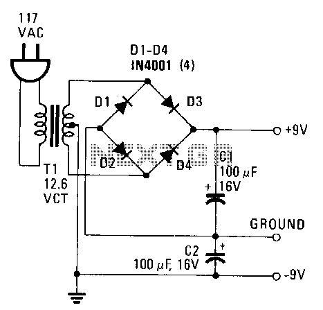
This power supply provides both +9 V and -9 V outputs to replace two 9-V batteries. The rectifier circuit consists of two separate full-wave rectifiers, each connected to the secondary winding of the transformer. The first full-wave rectifier, made up...
10 led simple roulette wheel circuit
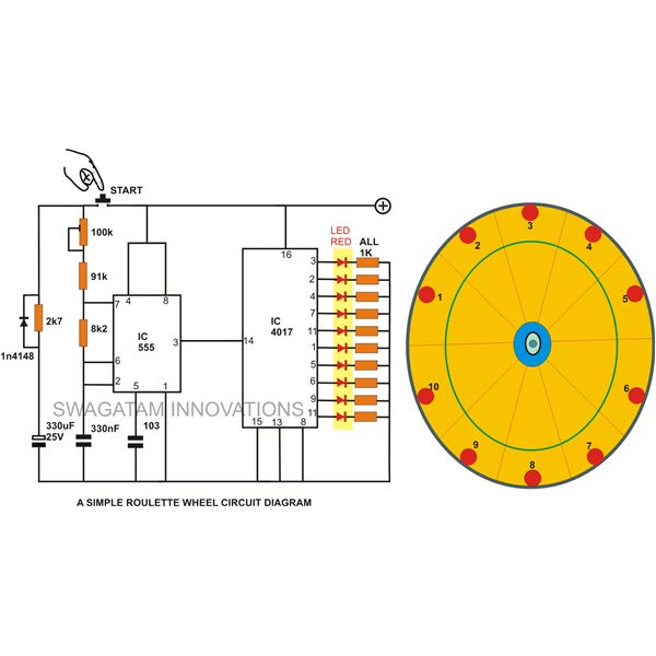
A simple circuit for a 10 LED roulette wheel is presented. Pressing the button initiates the LEDs in a rotational sequence that starts at full speed and gradually decelerates until it halts at a randomly selected LED. The randomness of...
White LED Night Light Circuit
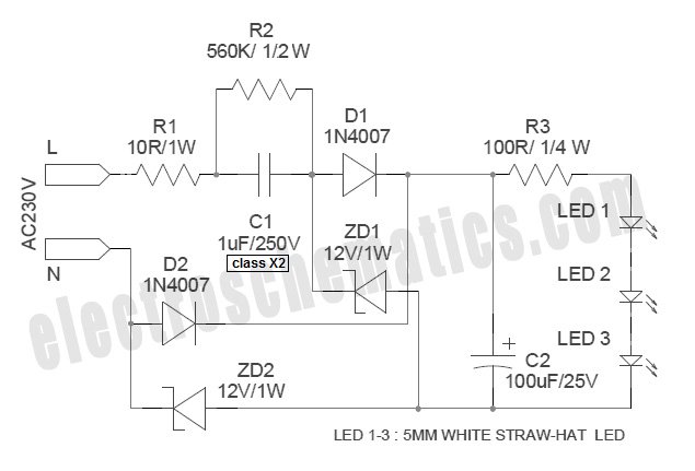
White Light Emitting Diodes (LEDs) now available can serve as a strong alternative to incandescent lamps in lighting applications. Today's White LEDs are...
White Light Emitting Diodes (LEDs) represent a significant advancement in lighting technology, offering energy efficiency, longevity, and reduced...

Multi-color LED driver
Have you ever wondered how many different colors can illuminate an LED? One, two, or maybe three? By constructing this simple circuit, you will discover much more. The key component in this design is a dual LED. This component consists...
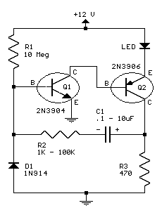
two transistor led flasher
This circuit will flash a bright red LED (5000 mcd) as an attention-getting device or fake car alarm. Component values are not critical, and other transistors may be used. The flash duration is determined by R2 and C1 and is...
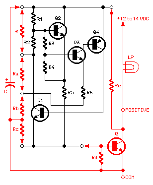
1.5V LED Flasher Oscillator
The 8-lead plastic mini-DIP LM3909 integrated circuit was developed by National Semiconductor in the mid-1970s. It is a monolithic oscillator specifically designed to flash Light Emitting Diodes (LEDs). By utilizing the timing capacitor for voltage boosting, it can deliver pulses...
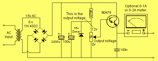
0-12V 2A power supply
This project has two options. It can be a mains operated project, using a 2155 or 2156 transformer or it can be connected to a plug pack. We recommend it be connected to a 16v AC 1 amp plug pack...
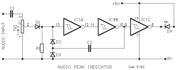
LED audio peak level
A peak level indicator when a signal exceeds a certain maximum value. It can be quite useful, for instance, with tape recorders, mixing consoles etc. One of the most important requirements of a peak level indicator is that it should...

Blinker Indicator
When the lamp turns off, a reset pulse is generated for the corresponding counter by NAND gate IC1. The counter then counts up again. The display's progression rate can be adjusted to the desired speed using potentiometer P1. Only one...