


Automatic Garden Lamp Simple Electronic Circuit Schematic for Turn-on and Turn-off Lamp Automatically
#LDR
#voltage divider
#automatic control
#light sensor
#circuit schematic
#garden lamp
#turn-on
#turn-off
#resistor
#lighting automation
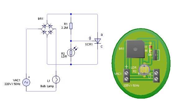
Description: Adjust the value of R1 to achieve optimal performance of the LDR sensor. If, in practice, a resistance of 2.2 MΩ still activates the lamp, it is possible to increase the value of R1 to a larger resistance of 2.2 MΩ. R1 and R2 are configured as a voltage divider, where R2 is the LDR whose resistance varies with light conditions. This variation alters the voltage across R2, which serves as the input to the gate. The circuit utilizes a silicon-controlled rectifier (SCR) or thyristor. If the voltage across R2 is too low, the SCR will close the circuit; conversely, if VR2 is high, the SCR will open the circuit. The SCR operates with a DC voltage of 220V and functions as an electronic switch, triggered by the gate. The SCR will open and close depending on the voltage from the gate terminal. When connected to a lamp (bulb lamp) and a 220VAC power source, the lamp will turn on and off automatically based on light conditions. If there is interest in this schematic for an automatic garden lamp and modifications to the schematic or PCB layout are desired, the original files for the schematic and PCB layout are available for free download. These files can be accessed using PCB Wizard software, as the schematic and PCB layout were designed with this tool. Figure 3 displays a sample of the PCB layout generated using the auto-route feature of PCB Wizard. The PCB Wizard software is also available for free download.
This circuit is designed to provide an automatic lighting solution based on ambient light conditions, utilizing a light-dependent resistor (LDR) and a silicon-controlled rectifier (SCR). The LDR (R2) acts as a sensor that detects light levels; its resistance decreases in bright conditions and increases in darkness. This change in resistance affects the voltage at the gate of the SCR, which controls the flow of current to the connected lamp.
The configuration of R1 and R2 as a voltage divider is crucial for setting the appropriate threshold for the SCR to trigger. By adjusting R1, the sensitivity of the circuit can be fine-tuned to ensure that the lamp operates correctly under various lighting conditions. If the LDR detects darkness and the voltage at the gate exceeds the SCR's threshold, the SCR will conduct, allowing current to flow to the lamp and illuminating it. Conversely, when the ambient light increases, the resistance of the LDR decreases, lowering the voltage at the gate and turning off the SCR, thus extinguishing the lamp.
The SCR's ability to operate at a DC voltage of 220V makes it suitable for directly controlling high-voltage lamps, providing a reliable solution for outdoor lighting applications. The design allows for an efficient and automatic response to changing light conditions, enhancing energy efficiency and convenience.
For users interested in customizing the circuit, the availability of original schematic and PCB layout files facilitates modifications. The use of PCB Wizard software not only supports the design process but also allows for easy adjustments and optimizations of the layout, ensuring that the final product meets specific requirements. The auto-route feature in PCB Wizard simplifies the layout process, making it accessible even for those with limited PCB design experience.Adjust value of R1 to get good performance of sensor LDR, if in your practice with 2. 2 M ohm still turn on the lamp you can add value of R1 with the large of 2. 2 M ohm. R1 and R2 is used as voltage divider. R2 is LDR that resistance will change when LDR in the dark or bright condition. And then it will change voltage in R2 as input of gate SCR or thyristor. If VR2 is too small SCR will close circuit and VR2 is high SCR will open circuit. SCR or Thyristor is operated with DC voltage 220 DC and will operate like electronic switch with triggered from gate. SCR will open and close depend of voltage from gate terminal. If the circuit and schematic connected with lamp (bulb lamp) and source voltage 220 VAC it will make lamp turn-on and turn-off automatically depend of dark or bright condition.
If you interesting with this circuit schematic of automatic garden lamp and want to modified the schematic or PCB layout, we provide you original file of Schematic and Layout PCB that you can download freely. To open this file you can use PCB Wizard software, because we design schematic and PCB layout using PCB Wizard.
Figure 3 is sample of PCB Layout that we generated using auto route from PCB Wizard. You also can take Free Download Software PCB Wizard from here.
This circuit is designed to provide an automatic lighting solution based on ambient light conditions, utilizing a light-dependent resistor (LDR) and a silicon-controlled rectifier (SCR). The LDR (R2) acts as a sensor that detects light levels; its resistance decreases in bright conditions and increases in darkness. This change in resistance affects the voltage at the gate of the SCR, which controls the flow of current to the connected lamp.
The configuration of R1 and R2 as a voltage divider is crucial for setting the appropriate threshold for the SCR to trigger. By adjusting R1, the sensitivity of the circuit can be fine-tuned to ensure that the lamp operates correctly under various lighting conditions. If the LDR detects darkness and the voltage at the gate exceeds the SCR's threshold, the SCR will conduct, allowing current to flow to the lamp and illuminating it. Conversely, when the ambient light increases, the resistance of the LDR decreases, lowering the voltage at the gate and turning off the SCR, thus extinguishing the lamp.
The SCR's ability to operate at a DC voltage of 220V makes it suitable for directly controlling high-voltage lamps, providing a reliable solution for outdoor lighting applications. The design allows for an efficient and automatic response to changing light conditions, enhancing energy efficiency and convenience.
For users interested in customizing the circuit, the availability of original schematic and PCB layout files facilitates modifications. The use of PCB Wizard software not only supports the design process but also allows for easy adjustments and optimizations of the layout, ensuring that the final product meets specific requirements. The auto-route feature in PCB Wizard simplifies the layout process, making it accessible even for those with limited PCB design experience.Adjust value of R1 to get good performance of sensor LDR, if in your practice with 2. 2 M ohm still turn on the lamp you can add value of R1 with the large of 2. 2 M ohm. R1 and R2 is used as voltage divider. R2 is LDR that resistance will change when LDR in the dark or bright condition. And then it will change voltage in R2 as input of gate SCR or thyristor. If VR2 is too small SCR will close circuit and VR2 is high SCR will open circuit. SCR or Thyristor is operated with DC voltage 220 DC and will operate like electronic switch with triggered from gate. SCR will open and close depend of voltage from gate terminal. If the circuit and schematic connected with lamp (bulb lamp) and source voltage 220 VAC it will make lamp turn-on and turn-off automatically depend of dark or bright condition.
If you interesting with this circuit schematic of automatic garden lamp and want to modified the schematic or PCB layout, we provide you original file of Schematic and Layout PCB that you can download freely. To open this file you can use PCB Wizard software, because we design schematic and PCB layout using PCB Wizard.
Figure 3 is sample of PCB Layout that we generated using auto route from PCB Wizard. You also can take Free Download Software PCB Wizard from here.
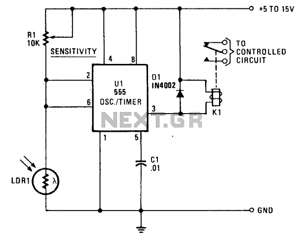
Photo alarm
LDR1, a cadmium sulfide (CDS) photoresistive cell, is utilized as the lower leg of a voltage divider between Vcc and ground. The timer terminals 2 and 6 are connected to the junction of the photocell and the sensitivity control resistor...
Light Sensor Switch Circuit
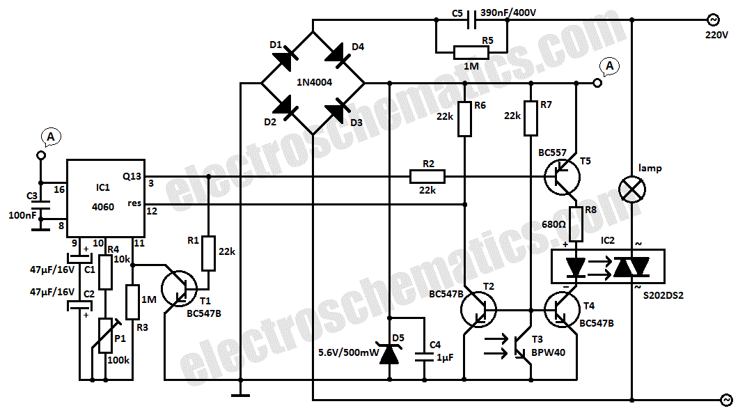
This light sensor switch circuit enables the automatic activation of a lamp when ambient light levels are low (such as during nightfall) and keeps the lamp illuminated for a specified duration. When transistors T4 and T5 are activated, the relay's...
Simple Light Sensor
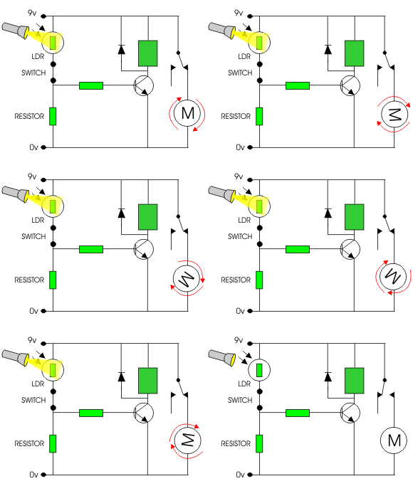
The following circuit illustrates a simple light sensor circuit diagram. Features include crocodile technology for simulating circuit operation, and an LDR (Light Dependent Resistor) is utilized.
The simple light sensor circuit operates on the principle of light intensity detection using an...
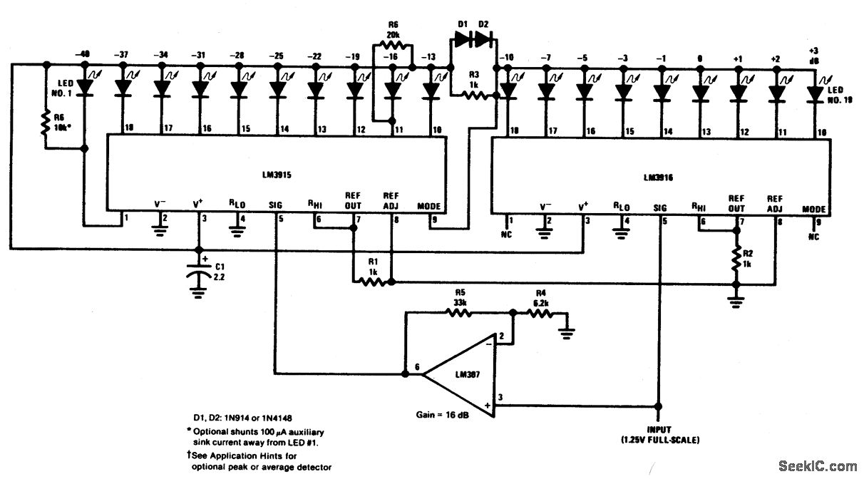
EXTENDED RANGE VU METER
This circuit can be utilized as a small beacon or marker light, as well as for toys or novelty items. R1 is a light-dependent resistor (LDR) that has a dark resistance of greater than or equal to 10 kΩ, or...
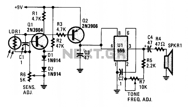
Sun wake-up call
A cadmium sulfide photocell (LDR1), which functions as a light-dependent resistor, is connected to the base and collector of an NPN transistor (Q1). When light strikes LDR1, its internal resistance decreases from a very high value (in darkness) to a...
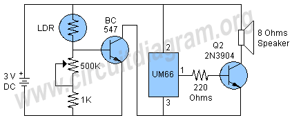
morning light activated alarm circuit
This project involves a light-activated alarm or morning alarm circuit that produces a pleasant melody upon detecting light. To use this circuit as a morning alarm, it should be placed in a location that receives morning sunlight. A 500K variable...
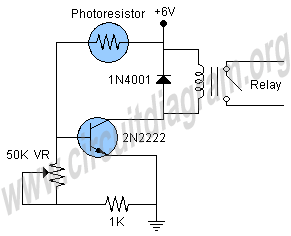
light sensor circuit
This is a light sensor circuit designed to detect light and activate a relay. The circuit is straightforward and requires only a few components. The operation of the circuit is simple: when the photoresistor detects light, it will turn on...
Light Sensor
The report provides information related to light sensors, photoresistors, comparators, and associated circuits. It contains extensive details regarding detection.
Light sensors are devices that detect and respond to light levels in the environment. A common type of light sensor is the...

light sensor circuit using pic16c63
This light sensor circuit, utilizing a photosensor, serves as a bridge between light and electronics. It is constructed using an operational amplifier and the PIC16C63 microcontroller to control the sensor. While the circuit is not intended for precision applications, it...