


Automobile White LED Light
#LED
#white LED
#battery power
#automotive lighting
#driver circuit
#efficient lighting
#DIY lighting
#power management
#LED modules
#automotive
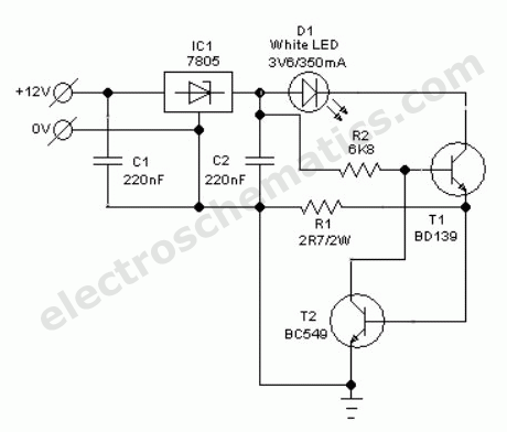
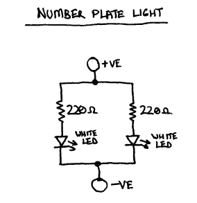
Description: Without a dedicated buck converter or white LED driver IC, it is possible to safely drive multiple standard high-efficiency white LED modules using available battery power.
To design a circuit capable of driving high-efficiency white LED modules without a dedicated buck converter or driver IC, a simple yet effective approach can be utilized. The circuit can be based on a linear regulator or a resistor-based current limiting method, depending on the specific requirements of the LED modules and the available battery voltage.
In this configuration, the power supply is connected directly to the LED modules. A current-limiting resistor must be calculated and placed in series with the LEDs to ensure they operate within their specified forward current ratings. The resistor value can be determined using Ohm's law, considering the supply voltage, the forward voltage drop of the LEDs, and the desired forward current.
For example, if the supply voltage is 12V, the forward voltage drop of the white LEDs is 3V, and the desired forward current is 20mA, the resistor value can be calculated as follows:
1. Determine the total voltage drop across the resistor:
V_R = V_supply - (number of LEDs × V_LED)
V_R = 12V - (3 LEDs × 3V) = 3V
2. Calculate the resistor value using Ohm's law (R = V/I):
R = V_R / I = 3V / 0.02A = 150Ω
In this example, a 150Ω resistor would be required. It is important to select a resistor with an appropriate power rating to handle the power dissipation, which can be calculated using P = I²R.
For applications requiring more precise current control or where the supply voltage may vary significantly, a linear regulator can be employed. The linear regulator will maintain a constant output voltage, allowing for consistent LED performance. The selection of the linear regulator should consider the maximum input voltage, output current requirements, and thermal performance.
In summary, this circuit design allows for the effective use of battery power to drive high-efficiency white LED modules without the need for specialized driver ICs, making it suitable for various applications where simplicity and cost-effectiveness are essential.Without any dedicated buck converter/white LED driver IC, you can safely drive many standard Hi-efficieny white LED modules using the battery power availab..
To design a circuit capable of driving high-efficiency white LED modules without a dedicated buck converter or driver IC, a simple yet effective approach can be utilized. The circuit can be based on a linear regulator or a resistor-based current limiting method, depending on the specific requirements of the LED modules and the available battery voltage.
In this configuration, the power supply is connected directly to the LED modules. A current-limiting resistor must be calculated and placed in series with the LEDs to ensure they operate within their specified forward current ratings. The resistor value can be determined using Ohm's law, considering the supply voltage, the forward voltage drop of the LEDs, and the desired forward current.
For example, if the supply voltage is 12V, the forward voltage drop of the white LEDs is 3V, and the desired forward current is 20mA, the resistor value can be calculated as follows:
1. Determine the total voltage drop across the resistor:
V_R = V_supply - (number of LEDs × V_LED)
V_R = 12V - (3 LEDs × 3V) = 3V
2. Calculate the resistor value using Ohm's law (R = V/I):
R = V_R / I = 3V / 0.02A = 150Ω
In this example, a 150Ω resistor would be required. It is important to select a resistor with an appropriate power rating to handle the power dissipation, which can be calculated using P = I²R.
For applications requiring more precise current control or where the supply voltage may vary significantly, a linear regulator can be employed. The linear regulator will maintain a constant output voltage, allowing for consistent LED performance. The selection of the linear regulator should consider the maximum input voltage, output current requirements, and thermal performance.
In summary, this circuit design allows for the effective use of battery power to drive high-efficiency white LED modules without the need for specialized driver ICs, making it suitable for various applications where simplicity and cost-effectiveness are essential.Without any dedicated buck converter/white LED driver IC, you can safely drive many standard Hi-efficieny white LED modules using the battery power availab..
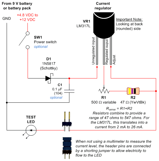
Constant Current LED Tester
Most circuits utilize a 5 V regulated power supply for microcontrollers and sensors, as 8-bit microcontrollers operate efficiently at this voltage. The 5 V supply is adequate for powering white LEDs, thus the specific voltage requirements of individual LEDs are...
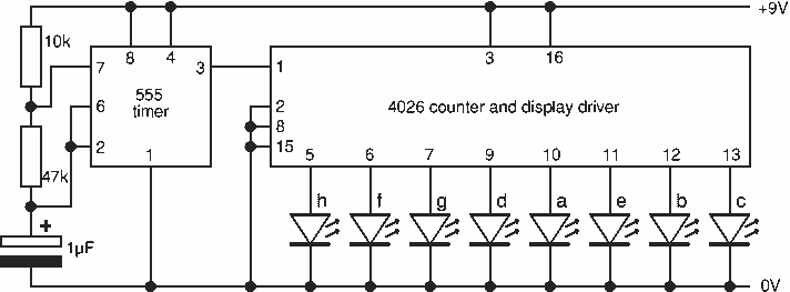
8 Random Flashing Leds Circuit
This project flashes eight LEDs in an apparently random manner. It uses a 4060 combined counter and display driver IC which is designed for driving 7-segment LED displays. The sequence is not really random because seven of the LEDs would...
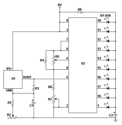
led thermometer pcb
Any LED can be used for D1 - D10; however, blue LEDs require a higher voltage, which may result in them appearing dimmer compared to red, yellow, or green LEDs. If pin 9 of U2 is left disconnected, the circuit...
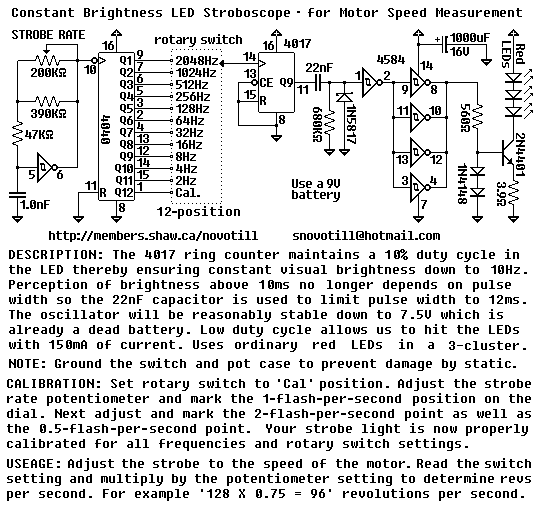
LED Stroboscope with EG1951-ND
The rotary switch is available for $5.00USD as of 2003 from DigiKey under part number EG1951-ND or EG1952-ND. It is a real pain to operate this circuit without a proper switch. You can put multiple 4017 ring counters in series...
led lighting for 6v vehicles
This design replaces the incandescent bulbs in the stop, tail, and indicator lights of an MZ or other motorcycle with a six-volt electrical system using high-intensity Lumiled LEDs. This modification offers several advantages: a single Lumiled consumes approximately 1.2W yet...
LED Flasher
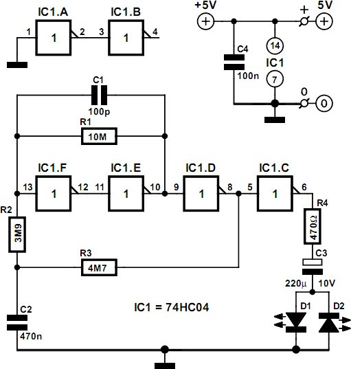
The concept of this economical flashing LED indicator is straightforward. It employs a low-frequency oscillator to drive two LEDs connected in anti-parallel. In the circuit diagram, it can be observed that the current flows for a brief duration with each...
Led Flasher with a BC547 NPN transistor
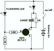
This is a novel flasher circuit using a single driver transistor that takes its flash-rate from a flashing LED. The flasher in the photo is 3mm. An ordinary LED will not work. The flash rate cannot be altered by the...
LED
This series of light switches operates differently from traditional voltage-based systems. These light switches can function directly on the AC power network. The primary components utilized in this circuit are a TRIAC and a Light Dependent Resistor (LDR). The circuit...
LED Chaser
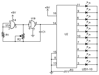
I don't know why, but people like blinking lights. You see LED chasers everywhere, in TV shows (Knight Rider), movies, and store windows. This schematic is my version of a simple 10 LED chaser. There is no 555 timer used...