


Bicycle rear-light afterglow
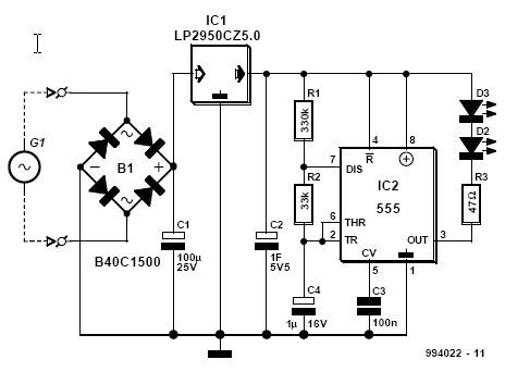
Description: This article is relevant only to readers whose bicycle lights are powered by a dynamo. The regulations regarding bicycle lights in the United Kingdom are stricter than those in other regions.
Dynamo-powered bicycle lights utilize a generator that converts mechanical energy from the bicycle's motion into electrical energy. This system typically consists of a dynamo, which is either hub-based or side-mounted, and a light fixture that incorporates LEDs or incandescent bulbs. The dynamo generates electricity as the bicycle wheels turn, providing a continuous power source for the lights without the need for batteries.
In the United Kingdom, regulations stipulate that bicycles must be equipped with functional lights when riding at night or in low visibility conditions. These lights must meet certain brightness and visibility standards to ensure safety for both the cyclist and other road users. Dynamo lights are advantageous as they eliminate the need for battery replacements, reducing waste and ensuring that the lights are always operational as long as the bicycle is in motion.
The circuit design for a basic dynamo-powered light system includes the dynamo, a rectifier to convert AC to DC, and a voltage regulator to ensure a steady output. The dynamo produces alternating current (AC), which can vary in voltage depending on the speed of the bicycle. The rectifier converts this AC to direct current (DC), which is then stabilized by the voltage regulator, ensuring that the light operates within safe voltage levels. Additional components may include capacitors for smoothing the output voltage and resistors for current limiting.
In summary, a dynamo-powered bicycle lighting system is an efficient and environmentally friendly way to ensure safety during night rides. By adhering to the strict regulations in the United Kingdom, cyclists can maintain visibility while contributing to a sustainable approach to cycling.This article is of interest only to readers whose bicycle lights are powered by a dynamo. The laws on bicycle lights in the United Kingdom are stricter tha.
Dynamo-powered bicycle lights utilize a generator that converts mechanical energy from the bicycle's motion into electrical energy. This system typically consists of a dynamo, which is either hub-based or side-mounted, and a light fixture that incorporates LEDs or incandescent bulbs. The dynamo generates electricity as the bicycle wheels turn, providing a continuous power source for the lights without the need for batteries.
In the United Kingdom, regulations stipulate that bicycles must be equipped with functional lights when riding at night or in low visibility conditions. These lights must meet certain brightness and visibility standards to ensure safety for both the cyclist and other road users. Dynamo lights are advantageous as they eliminate the need for battery replacements, reducing waste and ensuring that the lights are always operational as long as the bicycle is in motion.
The circuit design for a basic dynamo-powered light system includes the dynamo, a rectifier to convert AC to DC, and a voltage regulator to ensure a steady output. The dynamo produces alternating current (AC), which can vary in voltage depending on the speed of the bicycle. The rectifier converts this AC to direct current (DC), which is then stabilized by the voltage regulator, ensuring that the light operates within safe voltage levels. Additional components may include capacitors for smoothing the output voltage and resistors for current limiting.
In summary, a dynamo-powered bicycle lighting system is an efficient and environmentally friendly way to ensure safety during night rides. By adhering to the strict regulations in the United Kingdom, cyclists can maintain visibility while contributing to a sustainable approach to cycling.This article is of interest only to readers whose bicycle lights are powered by a dynamo. The laws on bicycle lights in the United Kingdom are stricter tha.
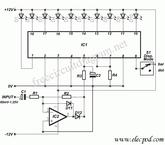
10 led VU Meter using LM3915
The circuit diagram represents a straightforward circuit-level indication featuring 10 LEDs. It utilizes a series of half-wave rectification controlled by the precision operational amplifier IC2 TL071. The LM3915 integrated circuit is employed to manage the LEDs, functioning as a VU...
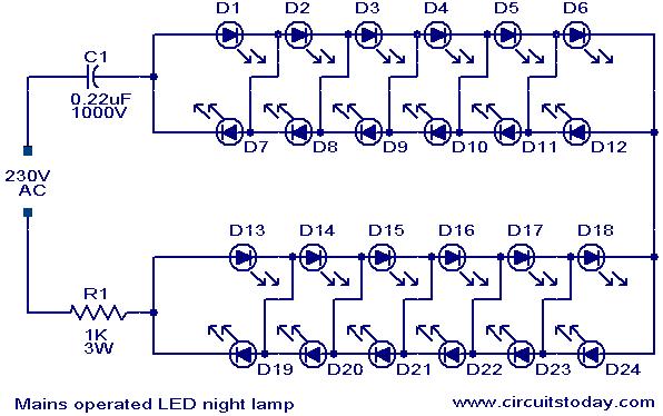
Mains operated LED night lamp
A simple and effective LED-based night lamp circuit is designed to operate directly from the 230V mains supply. The circuit utilizes a total of 24 white LEDs, producing an output of approximately 15W. Current limiting is achieved through resistor R1...
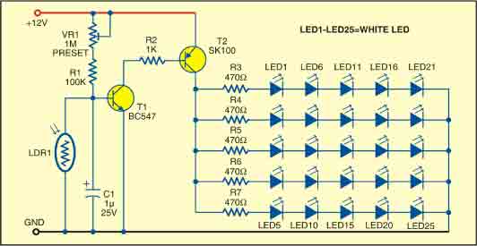
Simple Twi-light using white LEDs
This sunlight-controlled lamp utilizes a light-dependent resistor (LDR) as the sunlight sensor and comprises a total of 25 high-brightness white LEDs. Each row of LEDs is connected in series with separate resistors. The operation of the circuit is straightforward. During...
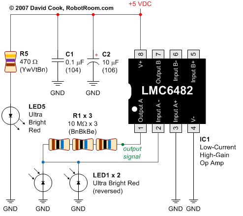
Using LEDs as colour sensors
This circuit converts the analog signal from the reversed LED, which is in sensing mode, and amplified by the operational amplifier, into a digital (on/off) signal. The original complex design has been simplified. An alternative approach is discussed in a...
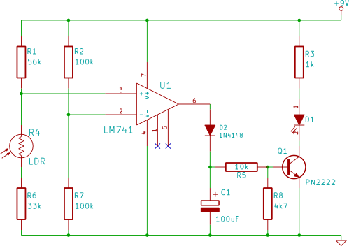
automatic light
This electronic breadboard circuit for beginners in electronics activates an LED automatically when the ambient light level falls below a specific threshold.
This circuit utilizes a light-dependent resistor (LDR) as the primary sensor to detect ambient light levels. The LDR is...
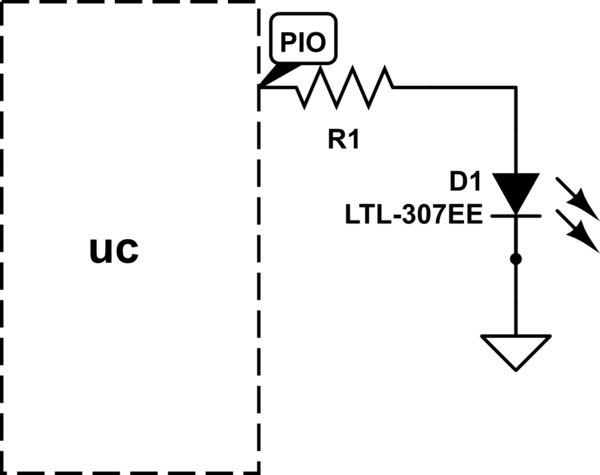
atmel driving LEDs directly from microcontroller pins
The LED will illuminate when the PIO (Programmable Input/Output) pin goes low, functioning similarly to a ground connection. In this configuration, the current is sourced from the power supply rather than the PIO, as in the first method. It is...
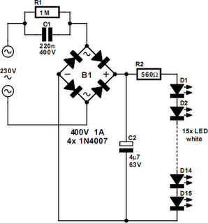
Mains Powered White LED Lamp
An array of white LEDs can serve as a compact lamp for living spaces. These LED lamps are commercially available and resemble standard halogen lamps, fitting into typical 230-V light fixtures. Upon inspection, it is evident that a capacitor is...
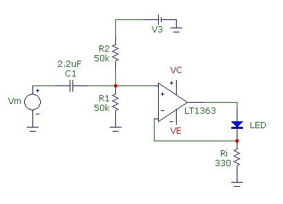
LED Modulation Circuits
Common Light Emitting Diodes (LEDs) require a direct current (DC) forward bias of 10 to 20 mA for optimal performance. The maximum allowable DC current typically ranges from 30 to 50 mA. The emitted light color, or wavelength, from an...
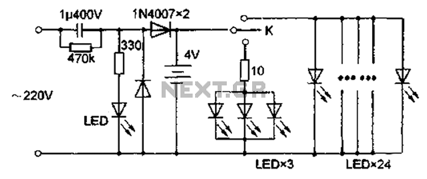
Comes with rechargeable lead-acid battery LED emergency light circuit diagram
The circuit diagram depicted in Figure 5 illustrates a system for charging a lead-acid battery using 220V AC power. The circuit employs a capacitor, buck converter, and diode rectifier for this purpose. A red LED indicates the charging status. When...